Inst ToolsInst ToolsInst Tools
  • Courses
  • Automation
    • PLC
    • Control System
    • Safety System
    • Communication
    • Fire & Gas System
  • Instrumentation
    • Design
    • Pressure
    • Temperature
    • Flow
    • Level
    • Vibration
    • Analyzer
    • Control Valve
    • Switch
    • Calibration
    • Erection & Commissioning
  • Interview
    • Instrumentation
    • Electrical
    • Electronics
    • Practical
  • Q&A
    • Instrumentation
    • Control System
    • Electrical
    • Electronics
    • Analog Electronics
    • Digital Electronics
    • Power Electronics
    • Microprocessor
  • Request
Search
  • Books
  • Software
  • Projects
  • Process
  • Tools
  • Basics
  • Formula
  • Power Plant
  • Root Cause Analysis
  • Electrical Basics
  • Animation
  • Standards
  • 4-20 mA Course
  • Siemens PLC Course
Reading: Single Push button to ON and OFF a Bulb using Ladder Logic
Share
Notification Show More
Font ResizerAa
Inst ToolsInst Tools
Font ResizerAa
  • Courses
  • Design
  • PLC
  • Interview
  • Control System
Search
  • Courses
  • Automation
    • PLC
    • Control System
    • Safety System
    • Communication
    • Fire & Gas System
  • Instrumentation
    • Design
    • Pressure
    • Temperature
    • Flow
    • Level
    • Vibration
    • Analyzer
    • Control Valve
    • Switch
    • Calibration
    • Erection & Commissioning
  • Interview
    • Instrumentation
    • Electrical
    • Electronics
    • Practical
  • Q&A
    • Instrumentation
    • Control System
    • Electrical
    • Electronics
    • Analog Electronics
    • Digital Electronics
    • Power Electronics
    • Microprocessor
  • Request
Follow US
All rights reserved. Reproduction in whole or in part without written permission is prohibited.
Inst Tools > Blog > PLC Tutorials > Single Push button to ON and OFF a Bulb using Ladder Logic

Single Push button to ON and OFF a Bulb using Ladder Logic

Last updated: March 4, 2021 3:28 pm
Editorial Staff
PLC Tutorials
13 Comments
Share
2 Min Read
SHARE

Learn how to use Single Push button to ON and OFF a Bulb using Ladder Logic in programmable logic controllers (PLC) control system.

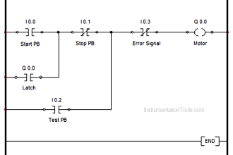
  • I0.0  : Input Push-Button (Normally-Open)
  • Q0.0 : Output Coil (Bulb)
  • Q1.5 & Q1.6 : Flags

Single Push button Ladder Logic

As soon as the push button I0.0 (N-O) is pressed ,it becomes N-C and coil Q1.5 (flag) is energized. The another flag Q1.6 will not energize as the output coil contact  Q0.0 is N-O, which breaks the circuit to the flag Q1.6.

As soon as the flag Q1.5 is energized ,the contact Q1.5 (N-O) becomes N-C and out bulb coil Q0.0 gets energized and bulb becomes ON.

Single Push button to ON and OFF a Bulb using Ladder Logic

Now, if the push button is released the coil Q0.0 will remain energized because of latching applied as latch contact Q0.0 (N-O) in last rung. To switch off the bulb the push button is again pressed which closes the N-O contact of o/p coil Q0.0 and energizes the flag coil Q1.6.

Due to energize of flag Q1.6 , the N-C contact of this flag in last rung becomes N-O  and as a result of this ,the last rung goes false and output coil Q0.0   is de-energized and bulb goes OFF.

If you liked this article, then please subscribe to our YouTube Channel for PLC and SCADA video tutorials.

You can also follow us on Facebook and Twitter to receive daily updates.

Read Next:

Motor Trip Logic using PLC

What is Relay Logic ?

Introduction to PLC Diagrams

PLC System Documentation

DeMorgan’s Ladder Diagram

Don't Miss Our Updates
Be the first to get exclusive content straight to your email.
We promise not to spam you. You can unsubscribe at any time.
Invalid email address
You've successfully subscribed !

Continue Reading

PLC Sinking and Sourcing Explanation
PLC Temperature Control using Pulse Width Modulation (PWM)
How to Run Multiple Motors with a Single VFD?
1 to 8 Demultiplexer PLC ladder diagram
PLC Sequential Operation Example Program
Features of SCADA
Share This Article
Facebook Whatsapp Whatsapp LinkedIn Copy Link
Share
13 Comments
  • Jakaria says:
    December 18, 2019 at 9:03 pm

    Very nc

    Reply
    • José Ignacio Theodor says:
      October 12, 2022 at 6:58 pm

      No funciona tal como está. Queda cambiando indefinidamente.
      El primer contacto I 0.0 no debe ser de estado ON, debe ser de flanco de subida.
      It doesn’t work just like that.
      It keeps changing state as long as the button remains ON
      You should change the I 0.0 button contact to be a rising edge detector.

      Reply
  • Sergey says:
    January 15, 2020 at 6:01 pm

    DO not fill people, this will not work.

    Reply
  • Raj says:
    January 16, 2020 at 10:38 pm

    This will not work….gave a try

    Reply
  • Brett says:
    March 21, 2020 at 9:41 am

    I’m no expert but this should turn it on, just to turn it right off again. Just based on me reading it. The bulb will open the top closed contacts to open, and the contacts below that to close, causing the second flag to get power. Once that gets power, it will then open it’s corresponding contacts, cutting off power to the bulb.

    So it will turn it on, then turn off. Basically flicker. Though maybe I’m wrong in my observation, though I don’t see how it could work regardless.

    Reply
  • Olgierd says:
    December 4, 2020 at 10:41 am

    This will cause output Q0.0 to flicker as it will be set in one program cycle just to get reset in next and again and again.
    You will need to add rising edge detection dor input I0.0 for it to work.

    Reply
  • Ilahi says:
    December 12, 2020 at 12:47 pm

    It’s a flicker for led not working properly as gets flick when turn on and similar when turning off.

    Reply
  • Novellus says:
    May 3, 2021 at 3:10 am

    I’m not understanding all the negative comments… I’m in CODESYS and this ladder seems to function exactly as shown…

    I did add a simple T_TRIG to my input signal to de-bounce the switch (pretty standard stuff when dealing with mechanical switches), but otherwise the ladder did exactly what the author claims. Win for me.

    Reply
  • Josue says:
    September 24, 2021 at 3:55 am

    No funciona

    Reply
  • Andy says:
    November 11, 2021 at 11:14 pm

    Below works. Basically a ring counter that just loops through counting from 1 to 2 due to successive button presses. 1. Press and hold to energize C01. 2. Release to energize CN01. 3. Press and hold to energize C02. 4. Release to energize CN02. 5. Press and hold to energize C01 (and so on, and so on…) You can use then use C01 and C02 as a momentary ON and OFF, or combine them as I’ve done to have a solid ON and OFF. For the bulb application, the bulb would be driven by C01 OR CN01.

    PB CN01 C02 C01
    —+-] [–+-]/[–+-]/[–+—(R)
    | |
    | C01 |
    +-] [–|

    PB C01 C02 CN01
    —+-]/[–+-] [–+-]/[–+—(R)
    | |
    |CN01 |
    +-] [———+

    CN01 PB CN02 C02
    —+-] [–+-] [–+-]/[–+—(R)
    | |
    | C02 |
    +-] [———+

    C02 PB CN02
    —+-] [–+-]/[–+—(R)
    | |
    |CN02 |
    +-] [–|

    C01 ON
    —+-] [–+—(R)
    | |
    |CN01 |
    +-] [–|

    C02 OFF
    —+-] [–+—(R)
    | |
    |CN02 |
    +-] [–|

    Reply
  • Andy says:
    November 11, 2021 at 11:21 pm

    It kind of works, mostly doesn’t. If you hold the push button down the bulb will go on and off repeatedly. When you release the button it just depends on timing whether it end up on or off. I’ve got a better way that is basically a ring counter that counts from 1 to 2 repeatedly due to successive button presses.

    Reply
  • Kavi says:
    July 8, 2022 at 8:13 pm

    If there’s a single switch as input,and 3 lamps as output..like…
    S1 is on-L1 on.
    S1 is off-L1 off.
    Again S1 is on- L1 still off and L2 is on.
    S1 off-L2 on.
    S1 on-L2 off,L3 on.
    S1 off-L3 off.

    What should be the ladder logic?

    Reply
  • Sundareswara Nathan says:
    July 3, 2023 at 8:21 pm

    I dont know, How people consider I0.0 as push button because rule for push button is, if the button is released it need to be in on state due to latch coil. Here no latch for I0.0. If we consider 2nd rung as latch network means it only flickers wont be in on or off state continuously.

    Reply

Leave a Reply Cancel reply

Your email address will not be published. Required fields are marked *

Stay Connected

128.3kFollowersLike
69.1kFollowersFollow
210kSubscribersSubscribe
38kFollowersFollow

Categories

Explore More

Best Way to Build Troubleshooting Mindset for Automation Engineer
What is Rewire Tool in Simatic Manager?
Equivalent Logic Gates using PLC Ladder Diagrams
Structured Text PLC Programming for Automatic Gate Control
Timer in Studio 5000 – TON, TOF, RTO
Electrical Cabinet Air Conditioner – Enclosure Cooling, Maintenance
Basic Pumping System Application Used in Industrial Automation
Evaluating Industrial Automation Projects Return on investment (ROI)

Keep Learning

Compare Servo Motor and Stepper Motor

Compare Servo Motor and Stepper Motor

Workstation Healthiness Checks

Workstation Healthiness Checks

Key Facts About RS485 Industrial Network

Key Facts About RS485 Industrial Network

PLC Ladder Program for Automatic Car Wash

PLC Ladder Program for Automatic Car Wash using Siemens TIA Portal

PLC Programming for Weight-Based Packaging

PLC Programming for Weight-Based Packaging

What is an instruction list language?

Structured Text vs. Instruction List for PLC Programming

Grounding or Earthing Scheme in DCS or PLC Systems

Grounding or Earthing Scheme in DCS or PLC Systems

Coil Type Timers in Siemens PLC Programming

Coil Type Timers in Siemens PLC Programming

Learn More

Voltage Divider

Voltage Divider

Advances in Control System

Fuzzy Logic Control

PLC Temperature Control using Pulse Width Modulation

PLC Temperature Control using Pulse Width Modulation (PWM)

Centrifugal Compressor outage reduced

Centrifugal Compressor Outage Reduced – Root Cause Analysis

Control Valve Passing Problem after Overhauling Job

Control Valve Passing Problem after Overhauling Job

Level Gauges

Level Gauge Design

Parts of Safety PLC

SIS Software Simulation – Safety Instrumented System

Process Variable Damping Graph

Process Variable Damping of Transmitter

Menu

  • About
  • Privacy Policy
  • Copyright

Quick Links

  • Learn PLC
  • Helping Hand
  • Part Time Job

YouTube Subscribe

Follow US
All rights reserved. Reproduction in whole or in part without written permission is prohibited.
Welcome Back!

Sign in to your account

Username or Email Address
Password

Lost your password?