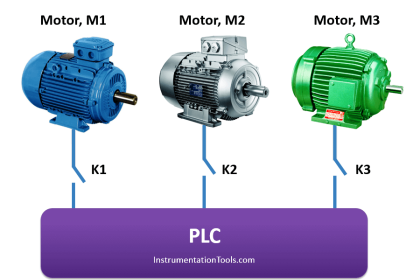
Many PLC configurations and standards are variable, even from a single vendor.
But, in each of these, there are common components and concepts. Sink & Source connections are these types of connections presented in most of PLC’s vendors.
Today we are going to learn how to make a Sink or Source connection and also, we will clarify the difference between both the connections.
Types of Input Signals
Inputs to, and outputs from, a PLC are necessary to monitor and control a process. Both inputs and outputs can be categorized into two basic types: logical and continuous.
Consider the example of a light bulb. If it can only be turned on or off, it is logical control. If the light can be dimmed to different levels, it is continuous. Continuous values seem more intuitive, but logical values are preferred because they allow more certainty, and simplify control.
As a result, most control applications (and PLCs) use logical inputs and outputs for most applications. Hence, we will discuss logical I/O and leave continuous I/O for later.
Inputs come from sensors that translate physical phenomena into electrical signals.
Typical examples of sensors are listed below in relative order of popularity.
- Proximity Switches – use inductance, capacitance or light to detect an object logically.
- Switches – mechanical mechanisms will open or close electrical contacts for a logical signal.
- Potentiometer – measures angular positions continuously, using resistance.
- LVDT (linear variable differential transformer) – measures linear displacement
continuously using magnetic coupling.
Difference Between PNP and NPN Sensors
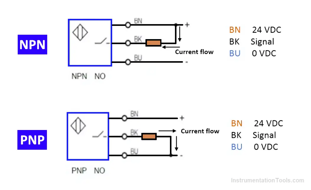
First of all, you have to notice that the difference between the sink and source connections depends on if you’re talking about PLC inputs or outputs, here we are talking about PLC inputs.
Considering the proximity switches as an example would help you to clarify this point.
We have two types of proximity switches (PNP – NPN):
Electrically, a PNP type of proximity switch outputs the current from the sensor with (+) voltage. An NPN type of proximity switch receives the current to the sensor with (-) voltage. As shown in Fig. (1).
Structure of Sink and Source sensors
Sinking sensors allow current to flow into the sensor to the voltage common, while sourcing sensors allow current to flow out of the sensor from a positive source.
For both of these methods, the emphasis is on current flow, not voltage.
NPN Sensor (Sinking)
As shown in Fig. (2) the sensor responds to a physical phenomenon. If the sensor is inactive (nothing detected) then the active line is low and the transistor is off, this is like an open switch.
That means the NPN output will have no current in/out.
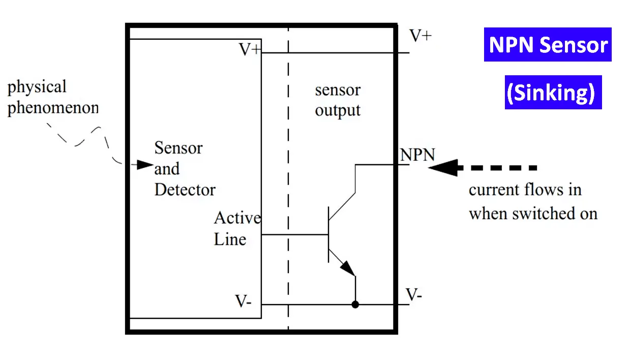
When the sensor is active, it will make the active line high. This will turn on the transistor and effectively close the switch.
This will allow current to flow into the sensor to the ground (hence sinking). The voltage on the NPN output will be pulled down to V-.
Note:
The voltage will always be 1-2V higher because of the transistor. When the sensor is off, the NPN output will float, and any digital circuitry needs to contain a pull-up resistor.
PNP Sensor (Sourcing)
Here in Fig. (3) we can see that the sensor responds to the physical phenomenon.
If the sensor is inactive (nothing detected) then the active line is low and the transistor is off, this is like an open switch. That means the PNP output will have no current in/out.
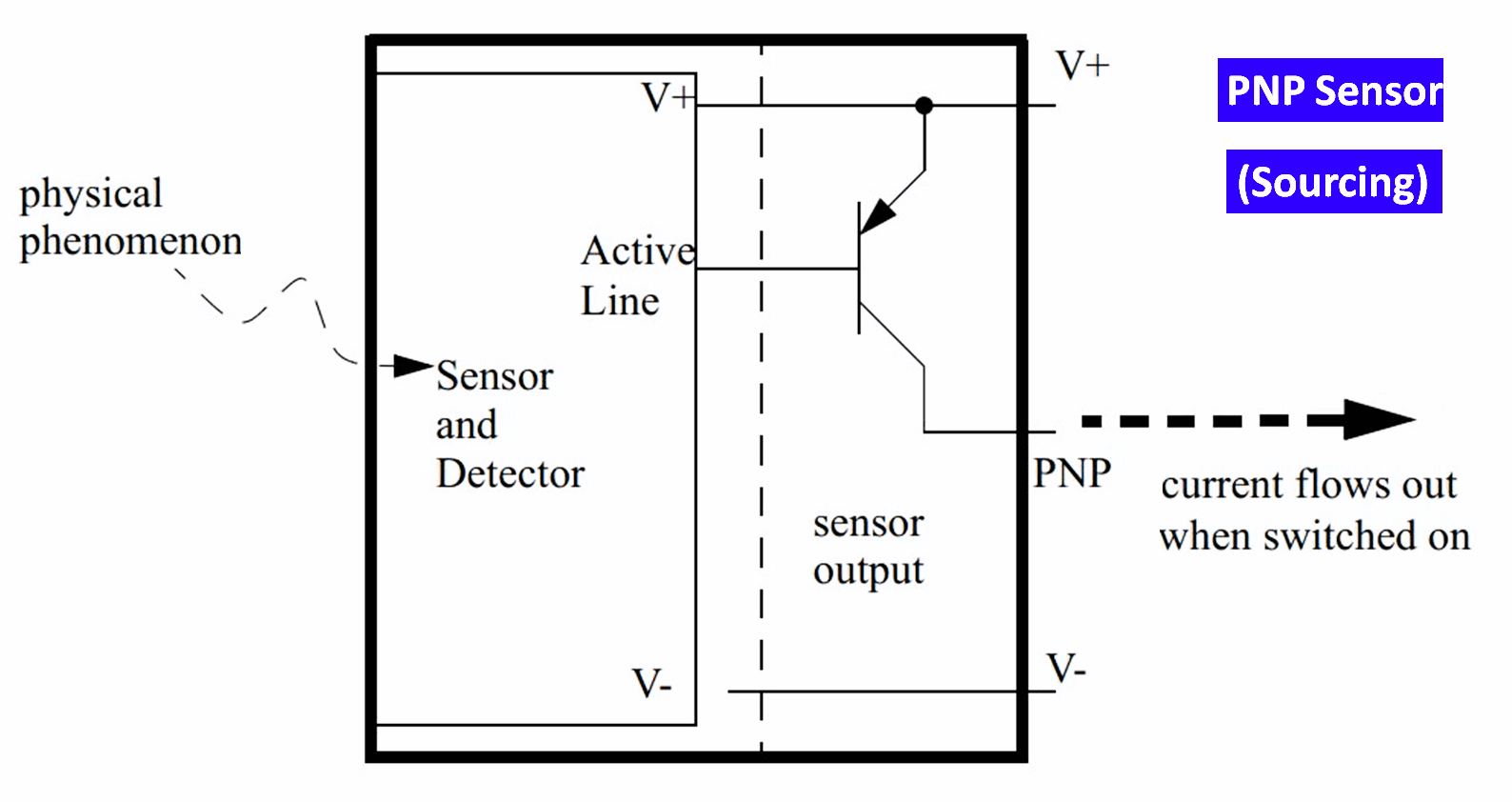
When the sensor is active, it will make the active line high. This will turn on the transistor and effectively close the switch. This will allow current to flow from V+ through the sensor to the output (hence sourcing). The voltage on the PNP output will be pulled up to V+.
Note:
the voltage will always be 1-2V lower because of the transistor. When off, the PNP output will float, if used with digital circuitry a pull-down resistor will be needed.
Resources
- Automating Manufacturing Systems with PLC.
If you liked this article, then please subscribe to our YouTube Channel for Instrumentation, Electrical, PLC, and SCADA video tutorials.
You can also follow us on Facebook and Twitter to receive daily updates.
Read Next:
- Scan Cycle in SIEMENS PLC
- Cloud-Based SCADA Projects
- PLC-based Gas Detection System
- Create New Project in Studio 5000
- Rockwell Allen Bradley PLC Projects


I like the question????
Perfecto, me gustó la aclaración. Muy útil para los trabajos que realizo. Muchas gracias.
Something not right. You keep saying for NPN and PNP “The voltage will always be 1-2V higher because of the transistor”
The NPN when active (base high) will short to GND with a voltage near 0. The PNP will conduct from V+ so when active (base low), it will provide a voltage within mV to V+.
Now, when not active the NPN output (collector) will float, so whatever pull up resistor will provide the voltage from the pull up voltage, that can be different from V+. The pull up will drop a bit of voltage by its resistive value and ohms law, but with a logic load that typically has high impedance, only millivolts are lost. Finally for PNP when not active is also floating, so a mid value pull down is needed to guaranty a logic 0 in the presence of leaks or noise.