In some industrial automation applications, you may need to operate more than one motor or pump in sequential order by the same digital input such as start push button.
Write a PLC program to run 4 motors in a case that every time you press the same push button it runs one motor at a time and then press the stop pushbuttons all motors should be stopped.
Note the best practice to learn the PLC programming is to start writing the PLC program, take your time before you review the answer.
Inputs & outputs:
- I0.0: Start (Normally open contact)
- I0.1: Stop (Normally closed contact)
- Q0.0: Motor_01
- Q0.1: Motor_02
- Q0.2: Motor_03
- Q0.3: Motor_04
- M0.0: marker for positive edge
- M0.1: marker for positive edge
- M0.2: marker for positive edge
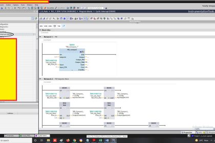
Run 4 Motors Sequentially from Same Push button
PLC Program
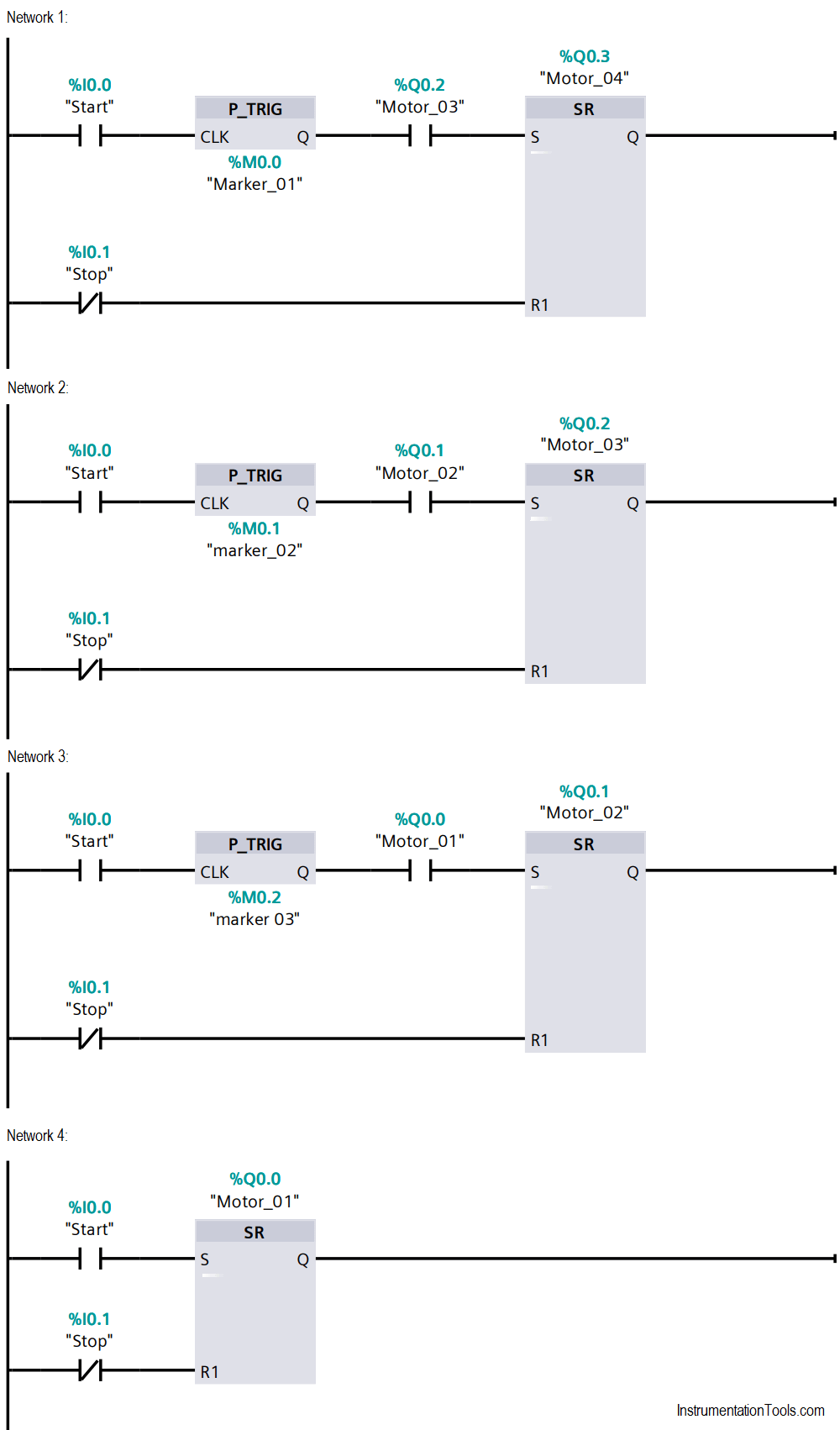
First network:
Motor # 04 will be on if the motor# 03 is on and a positive edge is detected from the Start Push Button. And will be off if the stop push button is pressed.
Second network:
Motor # 03 will be on if the motor# 02 is on and a positive edge is detected from the Start Push Button. And will be off if the stop push button is pressed.
Third network:
Motor # 02 will be on if the motor# 01 is on and a positive edge is detected from the Start Push Button. And will be off if the stop push button is pressed.
Fourth network:
Motor# 01 will be on if the start push button is pressed. And will be off if the stop push button is pressed.
Why we used positive edge detection? To avoid running all the motors in one time if the push button is pressed for the first time.
The order of all the networks is important. That’s why you can see the first network is dedicated to the 4th motor and so on, that’s because the fact that the PLC executes the program as the following it first reads all the inputs, then executes the program from the first network to the last network and then move the outputs values upon the program execution.
Author: Karim Ali Anwar
If you liked this article, then please subscribe to our YouTube Channel for PLC and SCADA video tutorials.
You can also follow us on Facebook and Twitter to receive daily updates.
Read Next:
- FC Function in Siemens
- Pulse Generation using PLC
- Motor Control Circuit
- Memory Structure of PLC
- What is Motor Jogging?