Hello guys and welcome back with another STL lesson, here is a series for you that illustrate basic knowledge for Statement list language that introduced for SIEMENS PLCs, and it is also the same as Instruction List language which is an IEC standard language.
So, if you are interested in this language you can check the previous articles:
Today we will be more familiar with this language by learning another important instruction in PLC programming which is Negative and Positive edges.
How does these instructions work? and what it can make for us? and how to perform these instructions using STL language? that what we are going to discuss so please keep focus.
What is the function of Positive & Negative Edges?
First of all, we have to functionally define these instructions:
Positive Edge Instruction
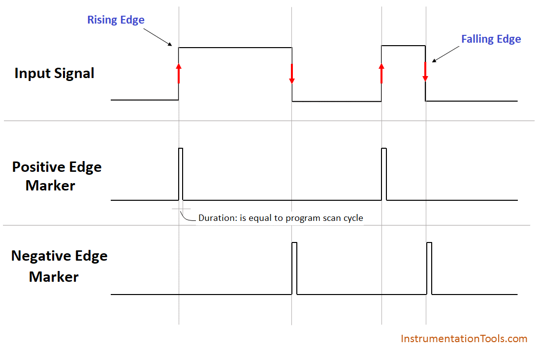
Positive Edge Instruction detects and waits till the Monitored signal is changing from “false to true” then this instruction fires a bit to be true for just one scan cycle and returns to zero again.
Negative Edge Instruction
Negative Edge Instruction detects and waits till the Monitored signal is changing from “true to false” then this instruction fires a bit to be true for just one scan cycle and returns to zero again.
Falling Positive & Negative by STL Language
Falling Negative using STL
Format
A <Input Bit>
FN <Bit>
Description
FN <Bit> (Negative RLO edge) detects a falling edge when the RLO transitions from “1” to “0”, and indicates this by RLO = 1.
During each program scan cycle, the signal state of the RLO bit is compared with that obtained in the previous cycle to see if there has been a state change.
The previous RLO state must be stored in the edge flag address (<Bit>) to make the comparison. If there is a difference between the current and previous RLO “1” state (detection of falling edge), the RLO bit will be “1” after this instruction.
Falling Positive using STL
Format
A <Input Bit>
FP <Bit>
Description
FP <Bit> (Positive RLO edge) detects a rising edge when the RLO transitions from “0” to “1” and indicates this by RLO = 1.
During each program scan cycle, the signal state of the RLO bit is compared with that obtained in the previous cycle to see if there has been a state change.
The previous RLO state must be stored in the edge flag address (<Bit>) to make the comparison. If there is a difference between the current and previous RLO “0” state (detection of rising edge), the RLO bit will be “1” after this instruction.
Application for Using FP & FN Instructions
In the below video, we explained the basic example and application usage of falling positive and falling negative instructions using a conveyor simulation.
If you liked this article, then please subscribe to our YouTube Channel for PLC and SCADA video tutorials.
You can also follow us on Facebook and Twitter to receive daily updates.
Read Next: