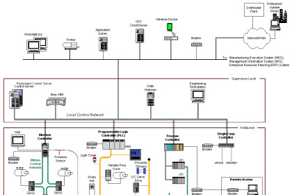
In our Automation world, there are two basic types of signals that manage the connection between the Field level (Instruments, Actuators) and the Control level, These two types which are (Analog, Digital) signals can utilize and transmit all you need to measure and monitor into your process (Level, Flow, Pressure…).
First of all, you should be aware of the difference between Digital and Analog signals… so, there is some difference between those two types of signals:
Digital Signals
Digital signals can provide you with just True or False state (1, 0) it could just tell you that there is something here or Not without knowing anything else, unlike the Analog signal which can provide you with detailed information about your measurand as the signal changes with time and it could have any value of (1, 2, 10, 30, 80, 100, 500, -20, 17.3 ……).
Analog Signals
Analog signals do not have any advantages over the Digital signal every signal has its own application, so if we have a tank and we want to know just if the tank is Full or Empty we can use level switches that utilize Digital signal But if we want to know how exact the tank level (10%, 30%, 70.7%, 87% ….) we should use Level Transmitter that utilizes Analog signals.
Analog Signal Classification
There are two basic concepts that you should know about any Analog Instrument:
- Instrument wiring type (2-wire, 3-wire, 4-wire)
- The Analog signal type (volt, ohm, milli Amps)
Instrument Wiring
The most popular sensor types are 2 wire, 3 wire, and 4 wiring methods.
2-wire Analog Sensors
Any instrument should have a power connection and also a signal connection the advantage of the two-wire Instruments, that the power and signal are merged into one connection so the instrument would have Two-wire that carry the power to the device and also the same two wires transmit the Analog signal.
Note: The corresponding Analog card that read the signal must have 2-wire connection feature.
Advantages of 2-wire Analog Sensors
- Uses only two wires which are costless and support easy wiring.
- Low power consumption
Disadvantages of 2-wire Analog Sensors
- The configuration is not suitable for power- hungry transmitters.
3-wire Analog Sensors
These types of instruments is not usually used as it considered complex when it compared with the two wiring devices.
In such a situation, the transmitter and receiver of the signal share a 0V line, and the other two wires are supplied by the transmitter to the PLC module.
4-wire Analog sensors
This method is used for instruments that have a slight high-power consumption so the power wiring is being separated from the signal wires.
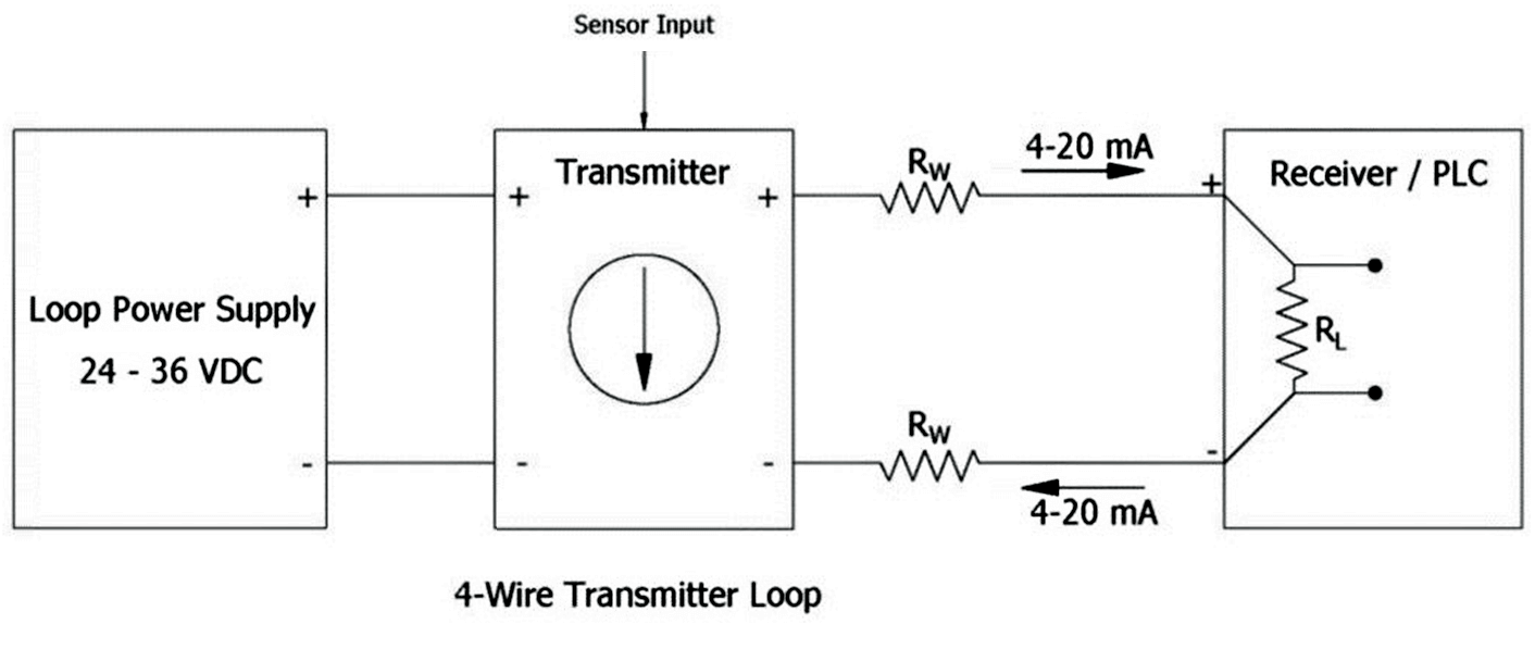
Advantages of 4-wire Analog Sensors
- 4 wire sensors wiring helps to eliminate the problem “Electric Interface”.
- Power isolation from Input-Output (IO) module would really help to build a reliable system.
Disadvantages of 4-wire Analog Sensors
- Requires additional cable cores.
- Requires a separate power supply for transmitter and controller.
Analog Signals Types and Ranges
There are three major mediums that can transmit an Analog signal such as:
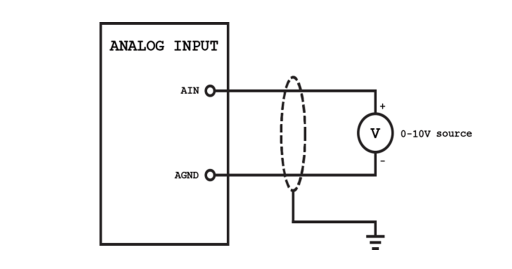
- Voltage ( 0 to 10V, 0 to 5V )
- Current ( 0 to 20mA, 4 to 20mA )
- Resistance
One of the reasons that make Automation Engineers prefer the analog current signals over the voltage signals is the Voltage drop in any plant there would be long distance between the field level and control level so in such situation the voltage drop that is dependent on the cable length (which by its role add some resistance) will annoy the analog signal that uses ( 0:10 V ) unlike the ( 4:20 mA ) as the current will not be affected by the cable length as it just needs a closed loop.
Another good point that should be mentioned is that why Automation Engineers prefer the (4:20 mA) over (0:20 mA), the answer is the “FAIL TO SAFETY” principle the Live zero indication in the (4:20 mA) signal which is 4 mA would really help you in case of wire break detection, so if any problem occurred to the wire the (4:20 mA) signal will detect that problem unlike the (0:20 mA) signal would have no change as 0 mA in the range of the signal.
The Analog instruments that depends on the Resistance changing is limited and have its own application such as ( Weight – thermal ) process measurements, these kind of instruments might also have some issue when using as the PLC can not differ the resistance of the cable from the resistance of the sensor so you might found the cable resistance adding some values on the actual value of the process.
Resolution of Analog Card
The Resolution expression is defined as the smallest change in the input signal that would be sensed by the
PLC card, you might have some Siemens Analog cards that are written into its description (8bit, 12bit, 14bit …) that is referred to the resolution of that card.
Assume we have 0 to 10V analog signal and also an analog card that has a resolution of 8 bit so the resolution will be calculated as follows:

Resolution = [10 – 0] / [(28) – 1]
Resolution = 10/255
Resolution = 0.0392 V
So, we can understand now from the previous equation that 0.0392V is the resolution which is the minimum change in the signal that could be detected by the PLC analog card.
Note It is preferred to have a high resolution into your PLC cards as that would give you a detail information about your measurands unlike when you have low resolution.
Calibration of Analog Instrument
Every piece of Analog Instrument into your plant must be calibrated, what is meant by calibration is that you adjust your signal levels with the actual process value, most analog instruments came without calibration so, the first thing you should know the calibration of the analog device.
There are two ways for calibration:
Local Calibration
In local calibration, we get into the instrument and adjust the zero-measuring point with the minimum signal level and the span measuring point with the maximum signal level, then the device automatically makes a linear relationship between the Measurand and the signal.
Calibrator
if your device supports HART protocol then you can use the calibrator to configure and calibrate your instrument.
Conclusion
Finally, we can say that if you have the option to select the analog instrument, the best choice for most application is the 2-wire instrument with ( 4:20 mA ) signal level, and also very important.
Note that you must ensure that the analog signal of your device is matching the selection of your PLC card.
If you liked this article, then please subscribe to our YouTube Channel for PLC and SCADA video tutorials.
You can also follow us on Facebook and Twitter to receive daily updates.
Read Next:
- FB and FC Programming in PLC
- Cyclic Interrupts in TIA Portal
- Problem on PLC, HMI, VFD
- Temperature Error of RTD
- 4-wire Transmitter Current Loop