All Industrial Process Plant Projects are designed and constructed to satisfy two main target goals: Risk/Safety Requirements and Process Performance.
Process Performance is followed and cared for mainly by PROCESS ENGINEERS, while Safety Requirements shall be considered and done by all project-responsible persons based on the known concept as:
SAFETY FIRST – ALWAYS SAFETY – SAFETY BY ALL
In fact, as Figure-1 shows Process Plant Risk/ Safety Management is the upper-level consideration for all technical and non–technical teams of the project, but to guarantee the achievement of a suitable safety level for Process Plant, one dedicated team as SAFETY-TEAM shall investigate and follow (supervise/ overlook) all safety activities.
Process Safety Roles & Responsibilities
Furthermore, as Figure 1 generally shows such a team shall follow and do some special activities and documentation by themselves too. In this article, we try to review some main activities and documentation of SAFETY-TEAM relevant to Process Safety Management in Detail/ Engineering Design Phase of a Process Plant Project.
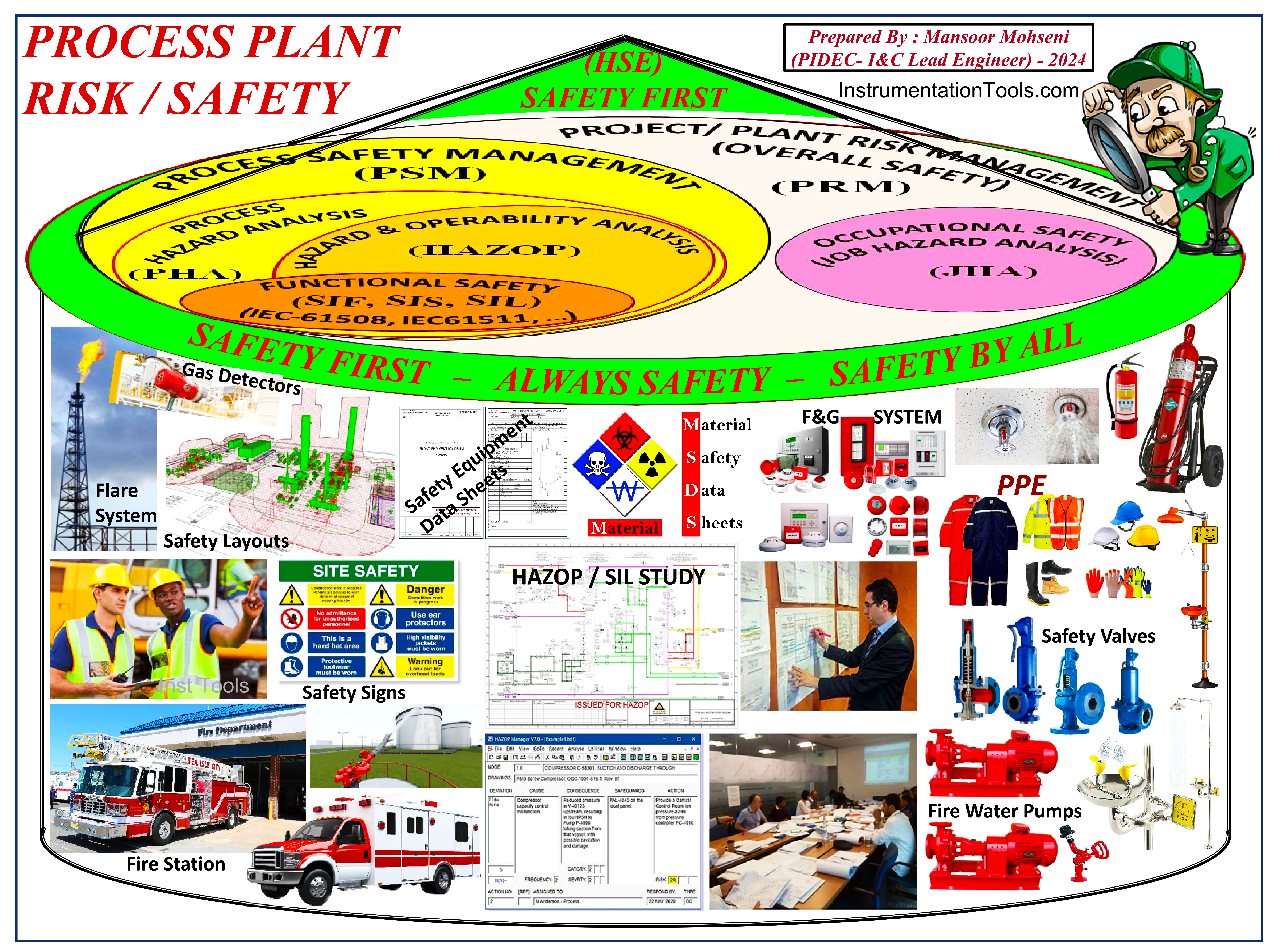
Figure 1: General Overview of Process Plant Risk / Safety (Management).
Process Safety Management (PSM) as Part of Project/ Plant Risk Management
Each Industrial Process Plant Project shall strictly follow Project/ Plant Risk Management (Overall Safety) due to compulsions of logical and forced laws or rules that are dictated by governmental or international associations/agencies. Project/ Plant Risk Management (PRM) has different parts and sections which shall be followed by all project persons and monitored by some administrator teams.
However, as Figure 2 shows, Project/ Plant Risk Management has two main goal categories as Process Safety Management (which relates to all safety requirements focused on Process Plant) and Occupational Safety or Job Hazard Analysis (which relates to all aspects of jobs/ human works).
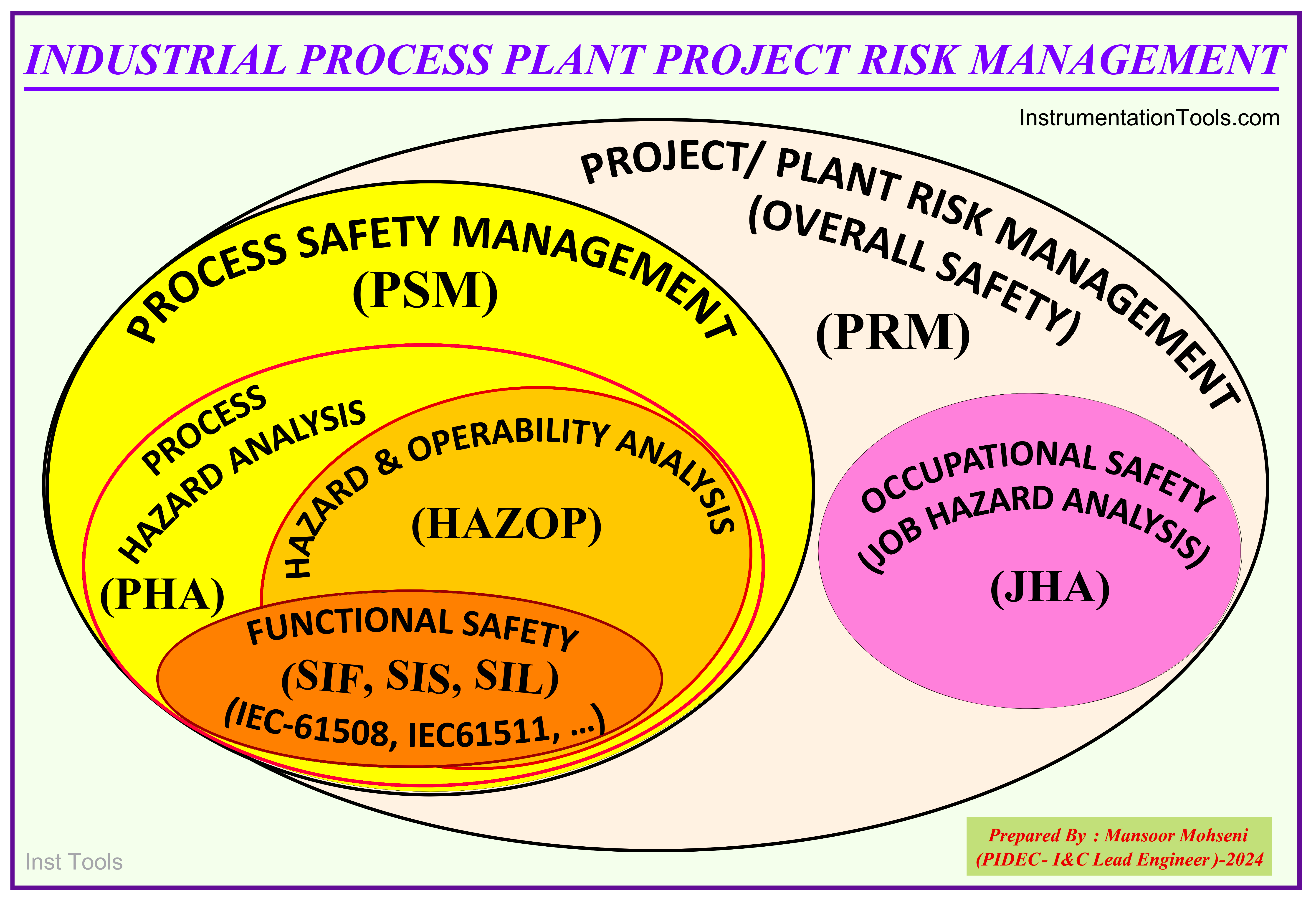
Figure 2: Industrial Process Plant Project Risk Management (Overview of Collection of Concerns).
Process Safety-team (Safety-team)
As mentioned, each required category of safety shall be administrated and monitored by someone responsible. Accordingly, Process Safety Management is administrated and followed by PROCESS SAFETY-TEAM or SAFETY-TEAM (as summarized form).
It is completely clear that (during the detailed design/ engineering and construction phase of the process plant) SAFETY-TEAM, first of all, shall be familiarized with all technical (chemical) processes concepts and material flows of the project plant and safety needs & requirements of activities and processes, and then trying to apply (and monitor) all relevant rules and procedures accordingly.
Since SAFETY-TEAM shall understand the processes of the project plant well, this team usually are selected from Process Engineers (and strengthened by other engineers or specialists).
In some Detail Design Engineering companies, the SAFETY-TEAM is part of the PROCESS Department, while in some other companies, the SAFETY-TEAM is managed by a separate department (i.e. SAFETY Department). However in some companies, there is no separate team as SAFETY-TEAM, but instead, all required activities will be done by PROCESS-TEAM. In some other companies, SAFETY-TEAM activities are divided between two or three departments.
Regardless of how SAFETY-TEAM activities and responsibilities are implemented, it is clear that such a team shall be familiar with the processes of the plant (and so the title of this article is selected as “Safety Roles & Responsibilities of PROCESS ENGINEERING”).
Usually during the Operation Phase of the Process Plant, SAFETY-TEAM is (strictly) separated from (the PROCESS) OPERATION-TEAM due to logical points, in order to prevent any hiding or cover of any fault/ guilt in case of an accident occurrence.
Safety-team Assignment as “HSE”
It is very important to know that the main target goals of SAFETY-TEAM roles and responsibilities are relevant to the protection of 3 main capitals /investments including: Health (humans and any lives), Safety (physical equipment or commercial items), and Environment (all perimeters or process surrounding items which have critical roles on the ecology of Earth Planet Life). Due to this concept, usually, SAFETY-TEAM may be called or assigned as HSE-TEAM (which is taken from the head letter of the three mentioned words).
In some cases “HSE” is selected as the abbreviation of Health Safety Execution, which again, means an execution team for the protection (Health and Safety) of all above mentioned three items.
Process Hazard Analysis (PHA)
Probably it can be said that the main roles and responsibilities of SAFETY-TEAM are reflected in the safety collection of aspects and concerns as Process Hazard Analysis (PHA), as shown in Figure-2.
In fact, by PHA, SAFETY-TEAM follows for doing a set of activities and producing documentation via help of other specialists and by using some tools or methodologies. During PHA, the main Hazards and Risks that may exist or be created in the Process Plant are specified (recognized) and listed by damage effects (due to severity and occurrence probability) – quantitatively or qualitatively- by using different methodologies or study procedures.(See Figure-3)
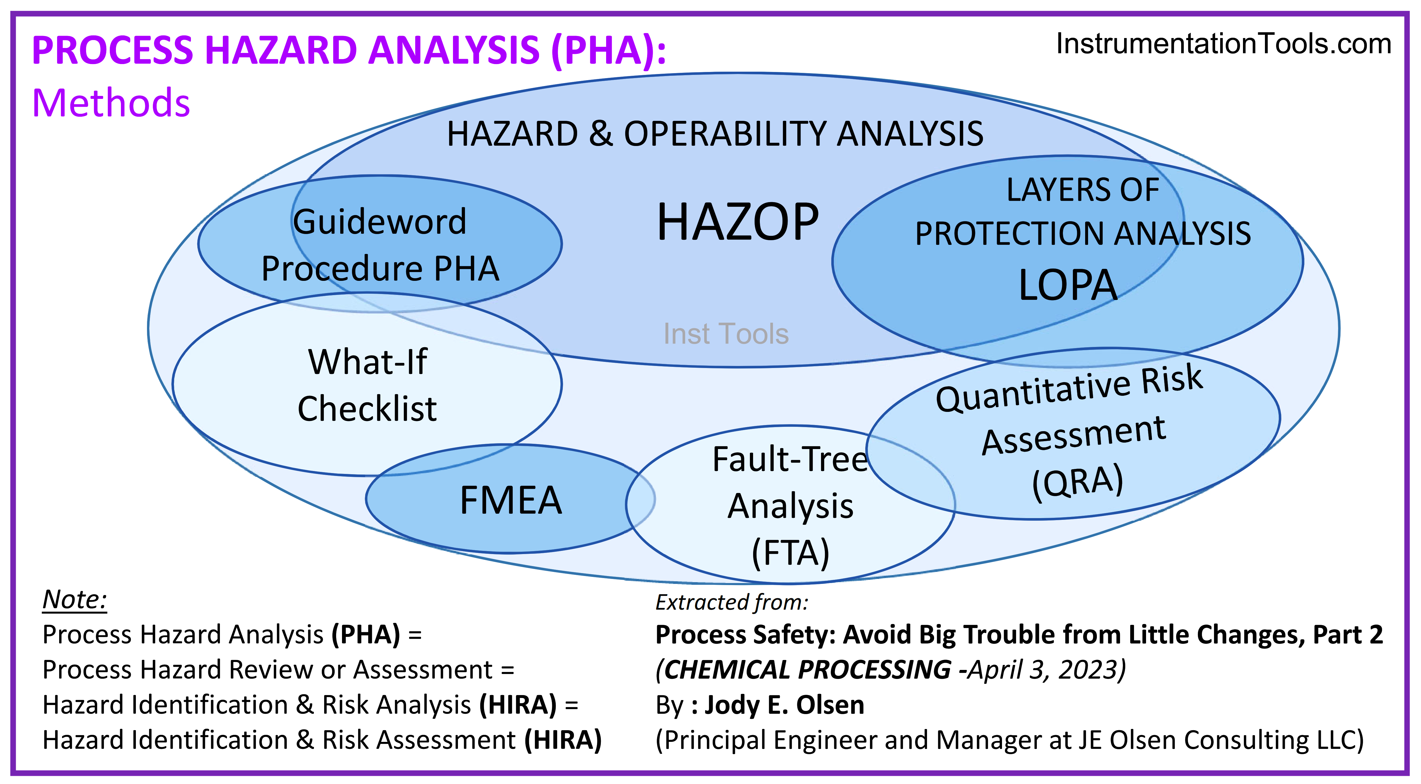
Figure-3: Different Methods in PROCESS HAZARD ANALYSIS (PHA).
As Figures 2 and 3 show Hazard and Operability (HAZOP) Analysis is one of the most common and usual methodologies which is used in PHA and is followed by Safety Integrity Level (SIL) Analysis.
During the HAZOP Study, control and safety loops that exist (or are needed) in the Process Plant are investigated for the satisfaction of the operator’s ability to control actions and monitor and protect processes and equipment due to any possible faults (no flow, high flow, low flow, …) by appearing suitable alarms or activating suitable interlocks.
HAZOP Study is a brainstorming meeting that is followed and configured by PROCESS and SAFETY Teams (usually as originators) with the attendance of other specialists. I&C-TEAM is one of the main attendances in HAZOP meetings to care and follow for selecting/ specifying and understanding suitable instruments and applying right interlocks and control and logical loops.
Following to HAZOP Study, the SIL Study is to be done in order to investigate the consequences of faulty (safety) instruments (in Safety Instrumented Functions = SIF) and measure how they can cause damage to humans, equipment/ capital, and the environment.
On the other hand, SIL Study is the methodology to measure the damage effects of safety instruments and investigate different levels of damages, and accordingly find suitable specifications (with having at least minimum required reliability) for that safety instrument or reducing the risks by hiring some compensation tricks. PROCESS and SAFETY Teams and also I&C Team are the main attendances of SIL Study meetings.
HAZOP and SIL Study meetings have detailed procedures and routines which cannot be explained here, but readers can refer to the mentioned references to be more familiar with the roles and responsibilities of the I&C Team and their interactions with PROCESS and SAFETY Teams.
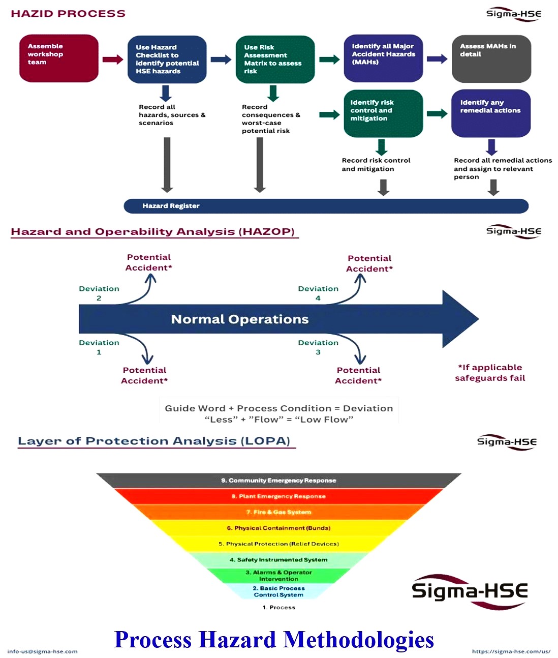
Figure-4: Overview of some methodologies that are used in PHA
Figure-4 shows a general overview of some methodologies that are used in Process Hazard Analysis (PHA). However, as Figure-3 shows there are many other methodologies that may be used during PHA their explanations are out of the scope of this article.
Safety Team Roles & Responsibilities
(This section is prepared via some extraction from: Detailed Design Engineering and Procurement (Project Standard and Specification)-Rev 07 document –Feb 2011, Issued by KLM Technology Group-Malaysia (karl@kolmetz.com))
Further to following Process Hazard Analysis (PHA), SAFETY-TEAM shall do some activities and accordingly produce some documentation for safety matters. They shall produce some Datasheets, Drawings, Lists, and documents and also coordinate with other disciplines for supplying Safety Equipment or implementing some Safety Functions (or procedures). We will review some of these roles and documentation here.
It shall be strictly mentioned here that (as already explained) some of the mentioned activities and roles may be done by PROCESS TEAM or even by other specialists due to different procedures/ practices or scope definitions in Detail Design Engineering companies.
Material Safety Data Sheet (MSDS)
All materials of processes that are applicable in the Process Plant shall be studied and reported as a datasheet/ list to specify and highlight the flame & explosion and toxic facilities of them in different conditions (especially during storing, transferring the materials, and use of them in process operations environments).
Also if some materials will be dangerous in the near location of some special materials shall be reported. On the other hand, SAFETY-TEAM shall develop safety data related to P&ID, review process design safety, and conduct a P&ID safety review.
Appling Safety Philosophy
SAFETY-TEAM shall:
- Review all project input data and documents from the point of view of project safety needs and provide a general overview of the project safety philosophy. Accordingly, they shall develop an Emergency Shut Down philosophy and review P&IDs for safe /reliable (and advanced process optimization) Start-up, Shut-Down, and Emergency Operations of each Process Unit to ensure that all necessary processing, utility, and blow-down piping and facilities are included for safe operation.
- Review alternative operations of the Process Units when associated Units may be shut down to ensure continuous and safe operation of each Unit.
- Make sure that applicable safety and loss prevention codes as well as the Company’s special requirements as expressed in the Safety Rules as mentioned in the contract are applied in a systematic and effective manner by safety audits during the engineering design phase.
- Provide necessary documentation to support safety case and certification submissions as required by the applicable legislation.
- Prepare and/ or complete the overall safety philosophy and based on this philosophy, the Contractor (SAFETY-TEAM) shall prepare separate detailed safety documents for each section of the project (for vendors of the package shall consider requirements accordingly). The said documents among other necessary information and Specifications shall include hazards and loss prevention data including plant layouts and arrangements, hazard sources and evaluation, area classifications, detection and alarm systems for specific events e.g., fire, gas release, shutdown, ESD (Emergency Shut Down) System, toxic gas release, fire protection systems both active and passive, firefighting equipment’s, means of escape, lifesaving appliances, drainage systems, ventilation, communication systems, navigation aids, regulations for effluent discharge, emergency power supply, sick bay, and first aid requirements.
- Preparing Safety Equipment Datasheets (and following documents for purchasing) including Relief Systems (relief valve specifications), Flare and relevant Knock-Out Drums, Safety Signs (Indicators), Fire Water Pumps, Safety Showers & Eye Wash Systems, …
- Foresee preparation of Logic Descriptions, Cause & Effect Charts; and preparation of safety documentation.
- Foresee preparation of layouts of Fire and Gas Detection Systems as well as fixed firefighting Equipment; collection of up-to-date vendor information; preparation of inquiry packages for loss prevention systems; review and approval of Vendor Drawings and Documentation.
- Making coordination and providing assistance/ services to other disciplines for doing their job responsibilities or providing their documentation.
- Generally for equipment to be purchased, to ensure that such equipment will perform satisfactorily within the system for which it is specified (especially from the safety point of view). Also, Safety Certificates and Calculations (including SIL Certificates and Validation Calculation) of all equipment/ instruments shall be collected to Project Safety Documents (as evidence for satisfaction of required safety requirements).
Hazardous Area Classification
SAFETY-TEAM shall have close coordination with EL-TEAM to specify different hazardous areas and zones and issue relevant (layout) drawing documents accordingly.
The final document(s) will be used mainly by I&C-TEAM for selecting and purchasing suitable instruments or accessory equipment (Isolator Barriers) at different specified areas.
Flare Requirements
Usually, Process Plant Projects may need Flare systems for depressurizing the process hazards (at critical process conditions) or venting to the atmosphere extra gases of processes (see Figure-5).
SAFETY-TEAM shall provide required calculations and drawings for specifying the right size (/ type) and location of required equipment.
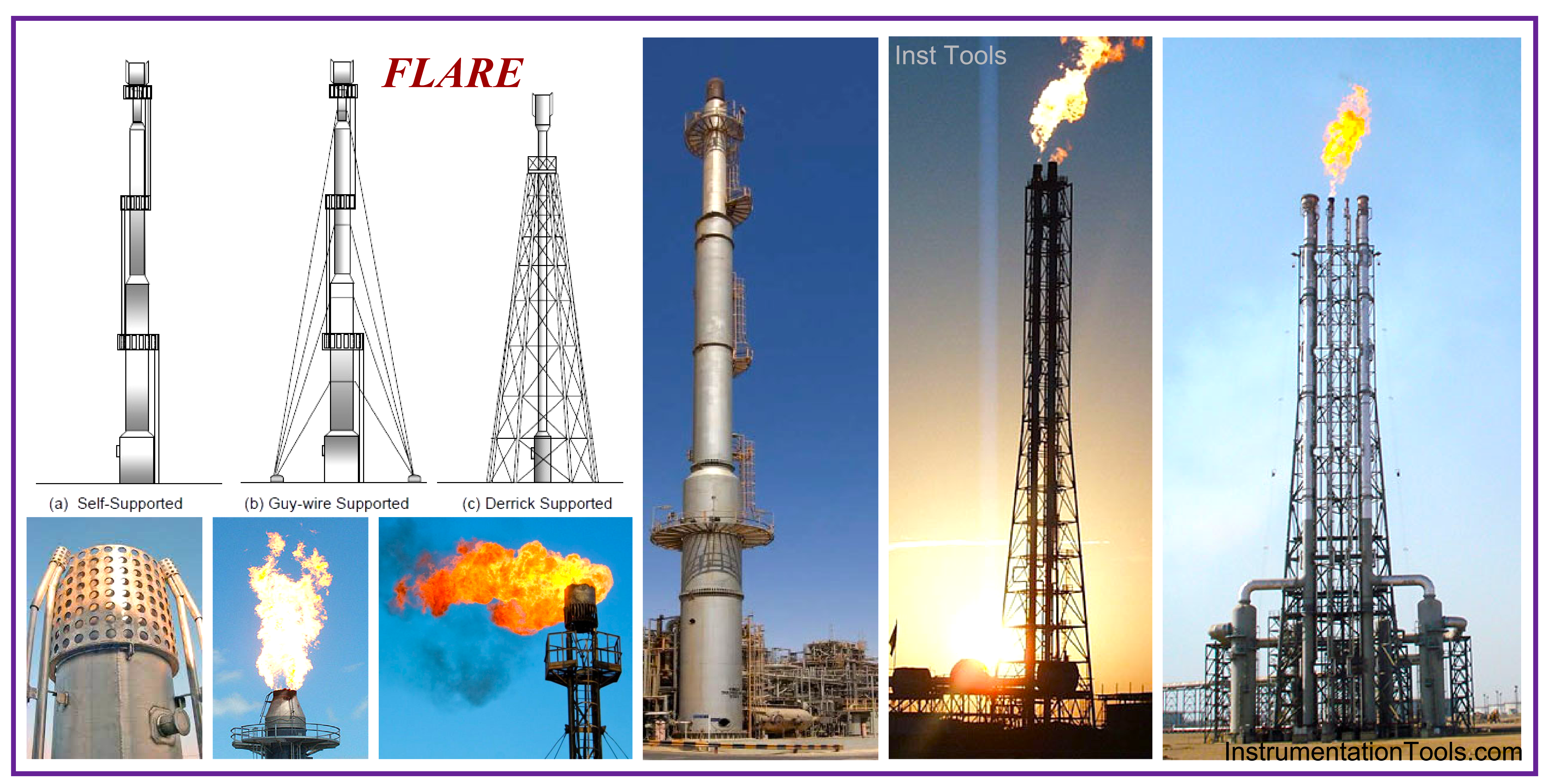
Figure-5: Flare System as a Usual Equipment in Process Plant Projects.
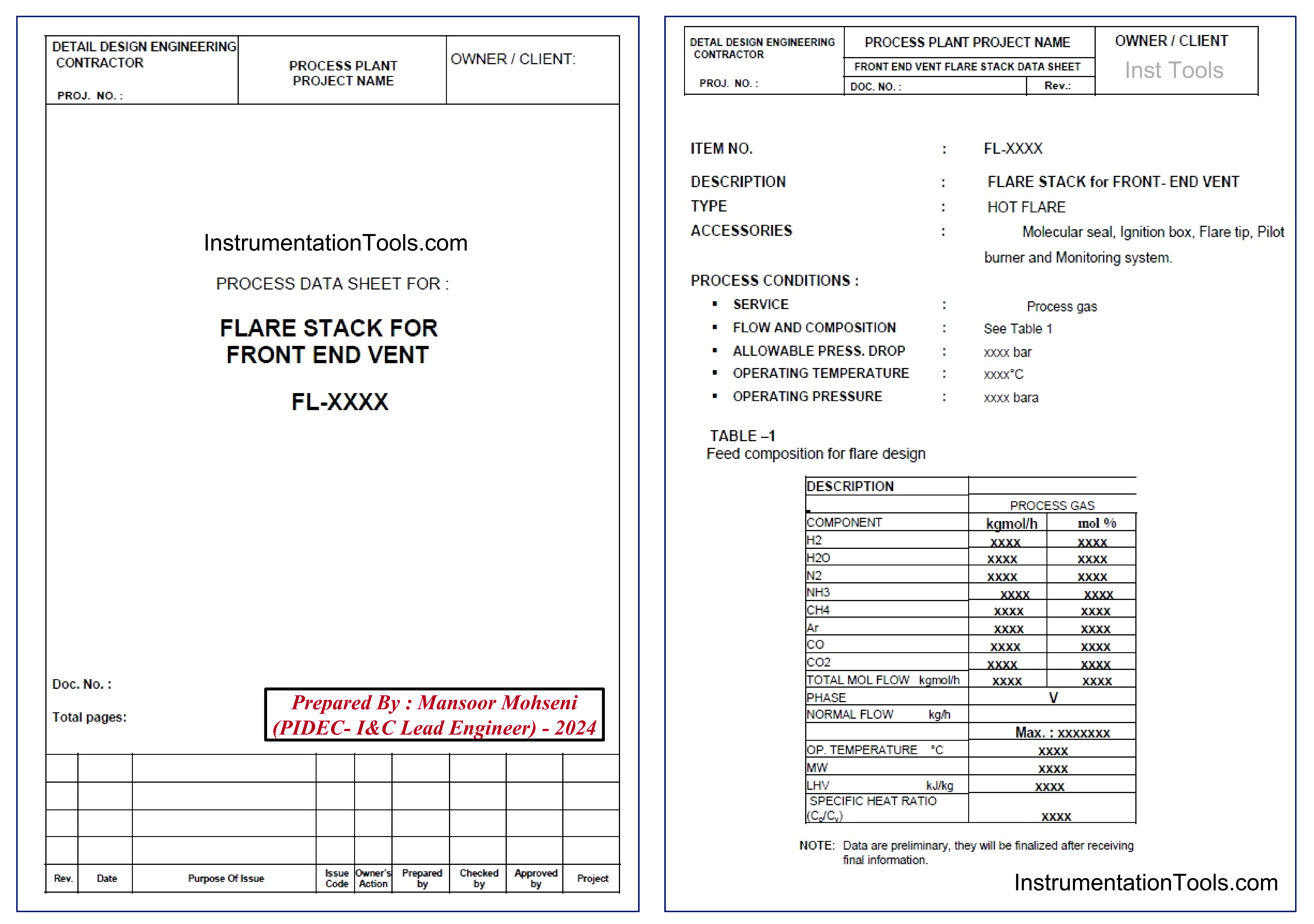
Figure-6: Sample of Flare Stack Datasheet in Process Plant Project.
Figures 6 and 7 shows two (extracted) sample datasheets for Flare Stack and relevant Knock-Out Drum.
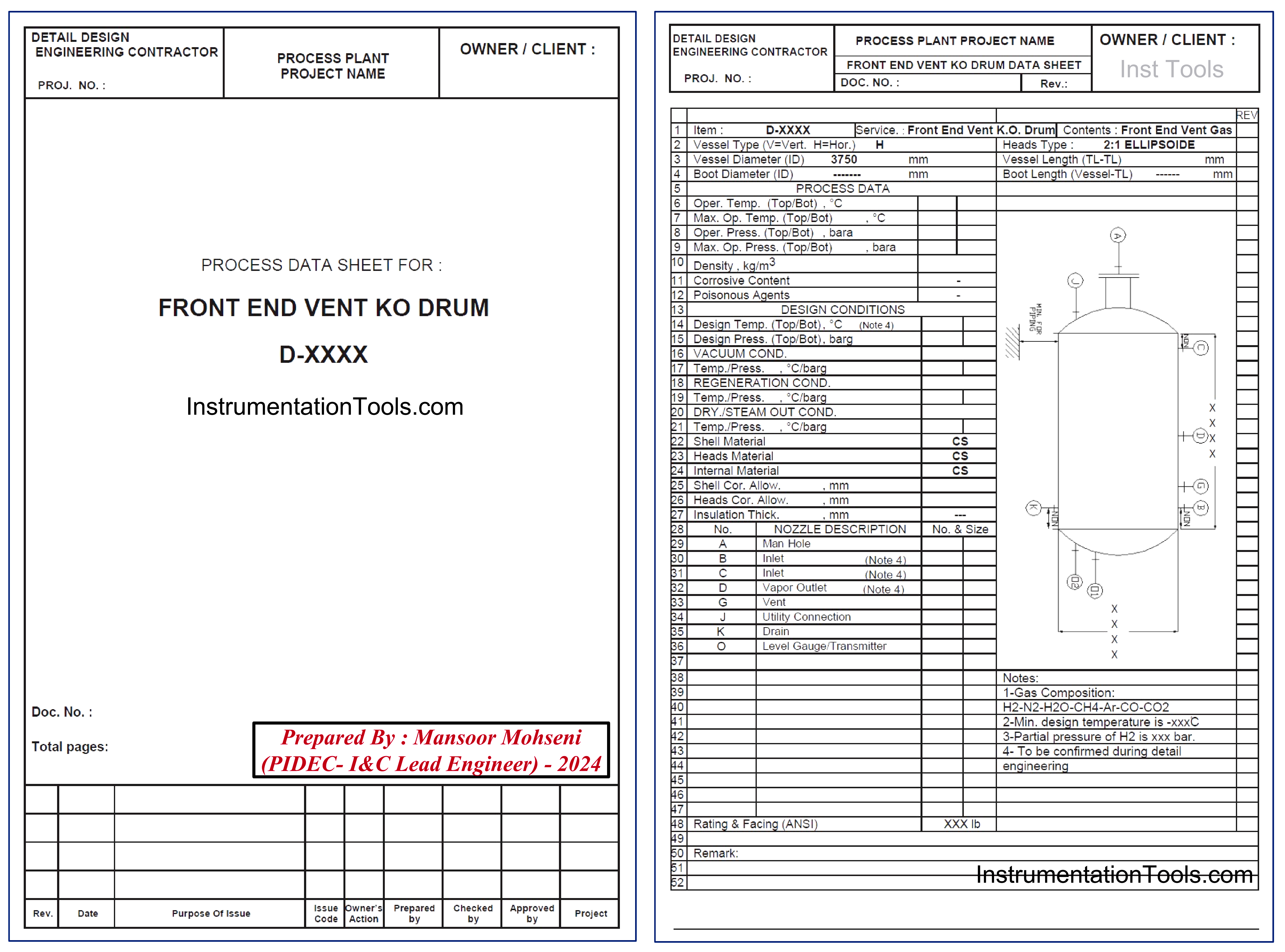
Figure-7: Sample of Vent Knock-Out Drum Datasheet in Process Plant Project.
Safety Layouts and Drawings
One of the main activities and documentations to be provided by SAFETY-TEAM are related to Safety Layouts and Drawings. Such activities include the below items but are not limited to:
- Safety P&IDs (Process Complementary P&IDs related to Safety items, as an example Waste Water Neutralization system)
- Deluge Valves P&IDs (see sample sheet shown in Figure-8)
- Safety Equipment Layout for showing the locations of Showers & Eye Washes and Portable and Wheeled Powder Extinguisher (See sample sheet shown in Figure-9).
- Site (Process Plant) Safety Detectors Layout for showing the location of Toxic/ Flammable Gas Detectors and Fire/ Flame Detectors further to Sounders and Light Beacons (See sample sheet shown in Figure-10).
- Offsite and Buildings (Electrical Substations, Control Rooms …) Fire Alarm Detectors Layout (See sample sheet shown in Figure-11).…
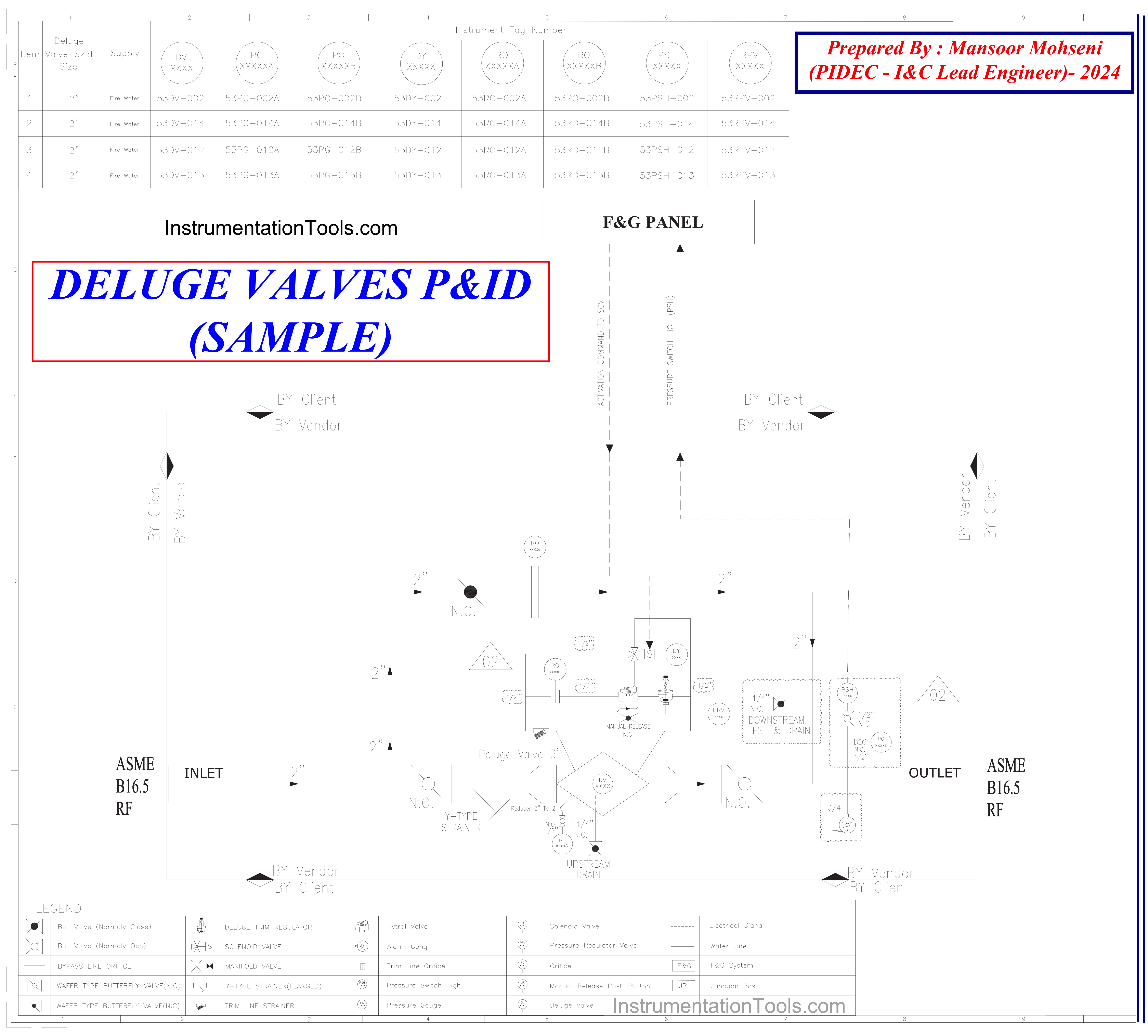
Figure-8: Deluge Valves P&ID sample which is provided by SAFETY-TEAM.
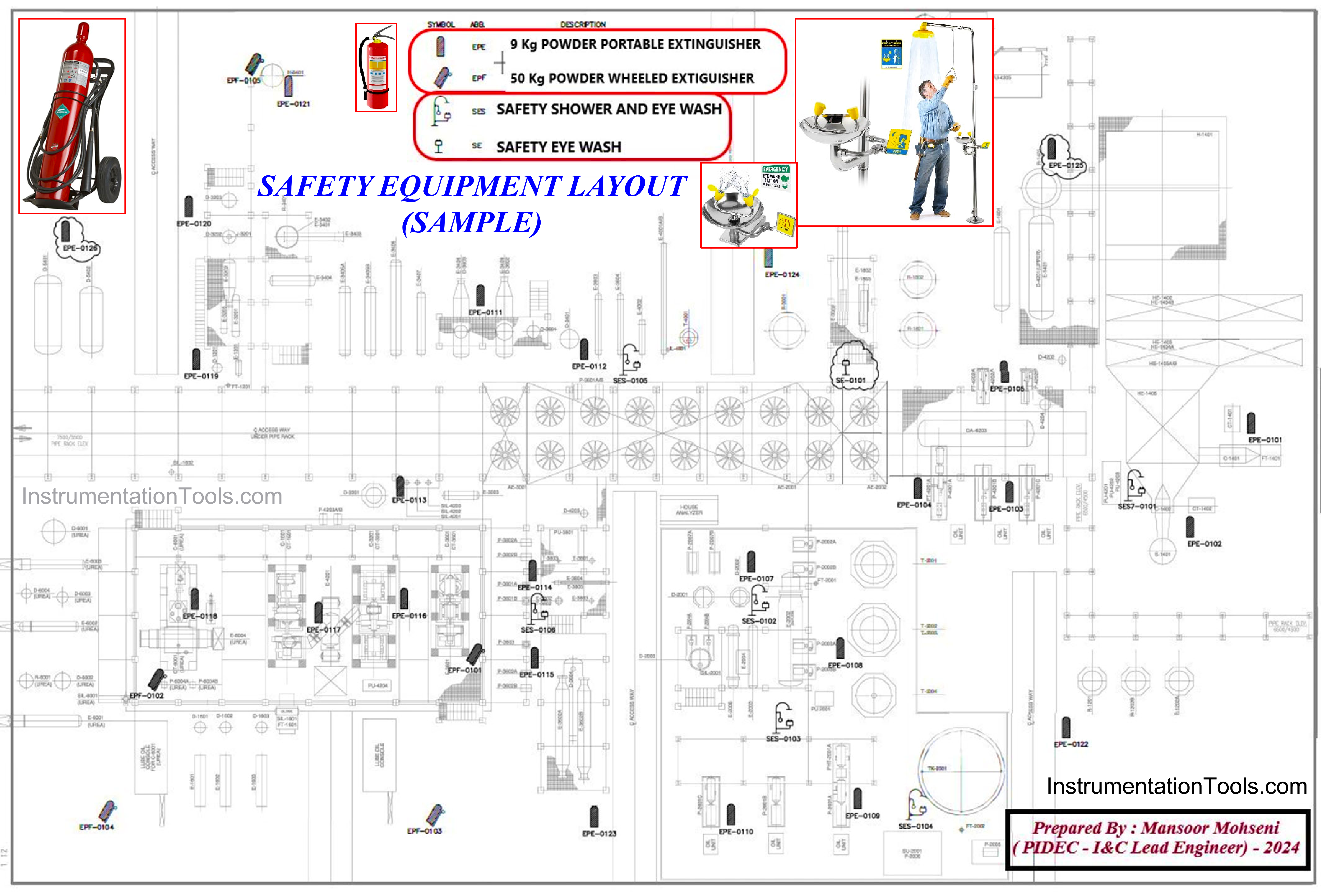
Figure-9: Safety Equipment Layout sample which is provided by SAFETY-TEAM.
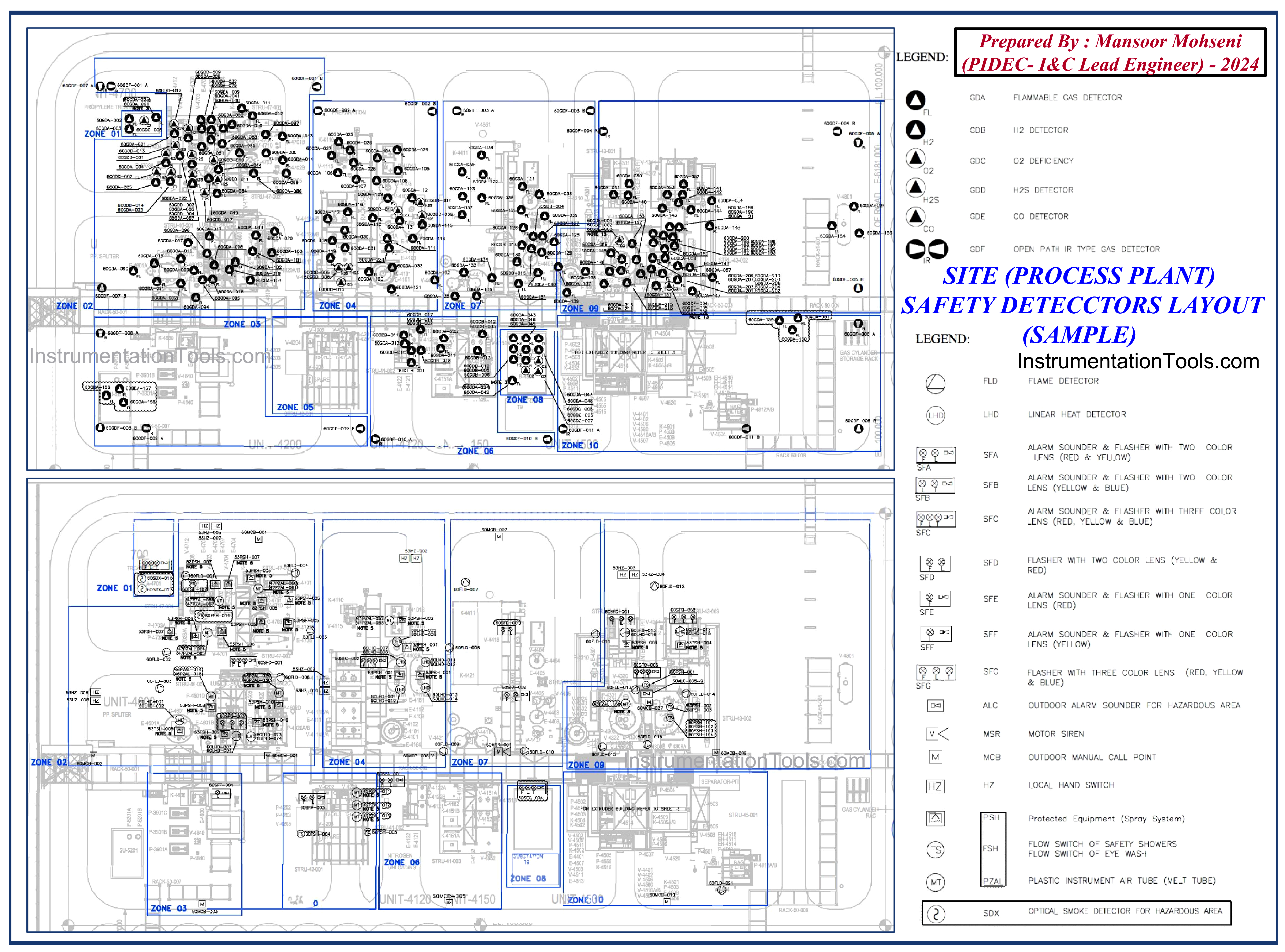
Figure-10: Site Safety Detectors Layout sample (by SAFETY-TEAM).
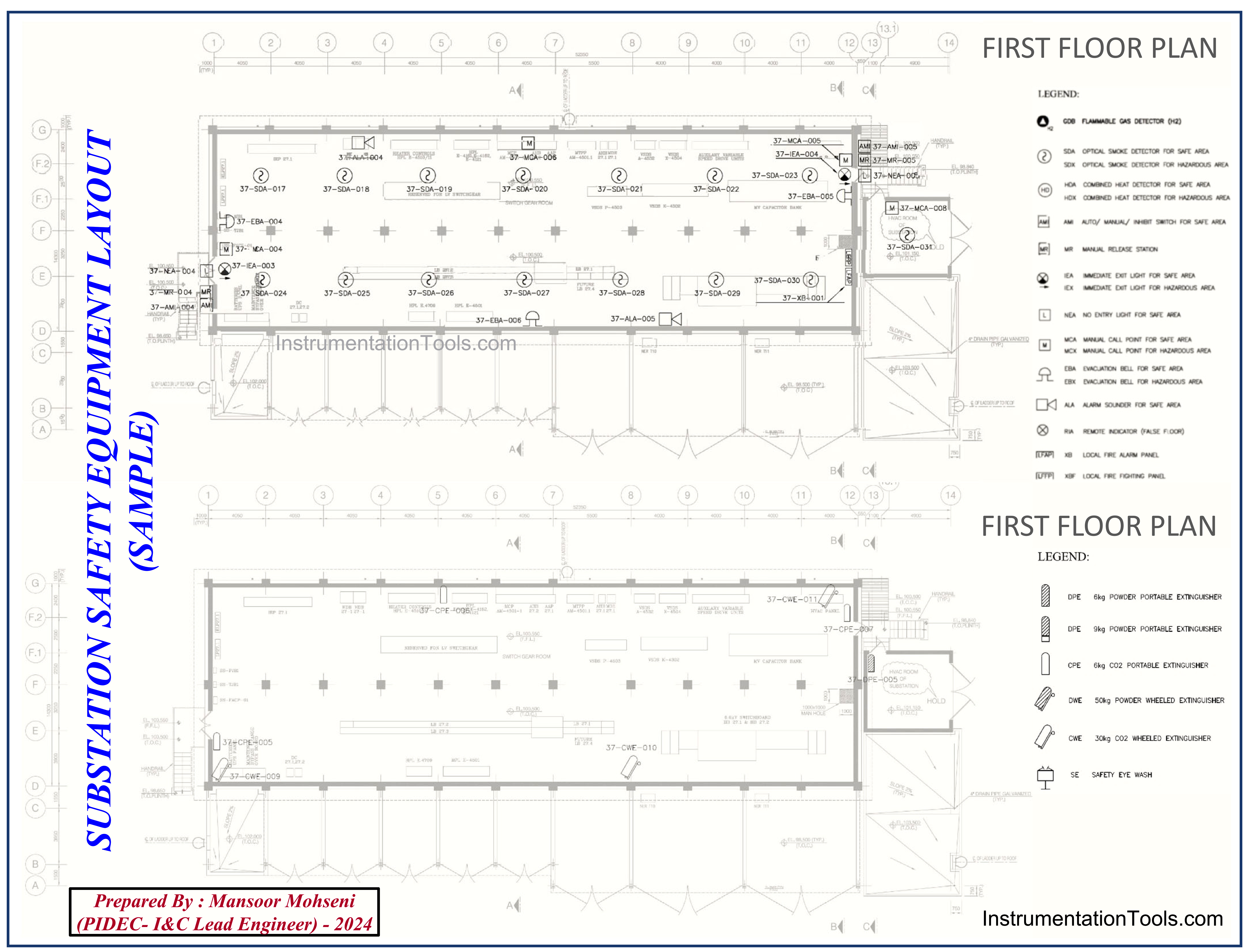
Figure-11: Substation Safety Equipment Layout (by SAFETY-TEAM).
Fire Fighting Systems
(This section is prepared via some extraction from: “The Oil & Gas Engineering Guide” book by Herve Baron)
Fire Fighting System of the Process Plant is designed by SAFETY-TEAM. Such a system comprises both passive and active firefighting means.
Active firefighting system consists of the fire water system, a pressurized water ring feeding hydrants, fire monitors (for manual firefighting) and the deluge system (for automatic fire fighting).
The deluge system consists of spray nozzles (sprinklers) arranged around the equipment that will automatically spray water on the equipment upon detection of fire. The detection itself is done by fusible plugs located around the equipment, which melt when subject to heat.
The purpose of the water spray is not to extinguish the fire, but to cool down the equipment, for instance, a pressure vessel, to prevent the steel from loosing its strength at elevated temperature which could lead to the collapse of the vessel and loss of containment.
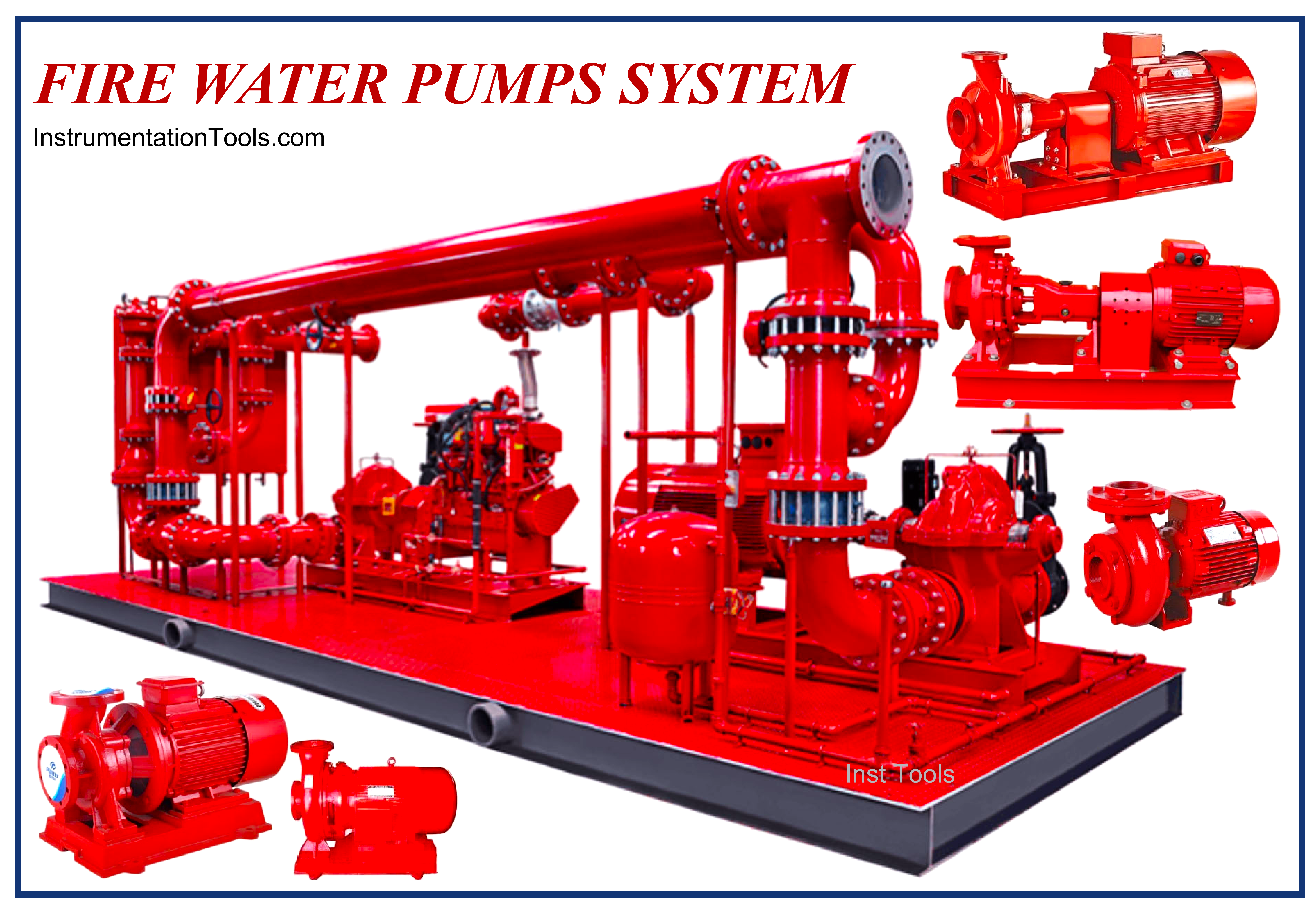
Figure-12: Fire Water Pumps System (by SAFETY-TEAM).
The quantity of firefighting water is determined in the fire water demand calculation note (see Figure-12). The plant area is first divided into fire zones. The water demand calculation is then calculated on the basis of a fire in one of the fire zones, with all firefighting equipment in operation in this fire zone. The deluge water demand is calculated from the number of sprinkler nozzles, itself a function of the surface areas of the protected vessels.
The fire water system is depicted by the SAFETY-TEAM on the fire water P&ID. The location of the firefighting equipment is shown on the Safety Equipment Layout.
SAFETY-TEAM based on the results of studies, then provide required datasheets for the Fire Water (Pump) system, and other relevant documents for purchasing such systems.
Fire Extinguishers
SAFETY-TEAM shall study the plant layout and consider suitable locations for the installation of Fire Extinguishers. Based on the area and available spaces, such extinguishers may be portable or wheeled (see Figures 9 and 11).
For extinguishing facilities of critical buildings (like CCR and Electrical Substations), SAFETY-TEAM shall provide (design and supply) a suitable Inert Gas Network as shown in Figure-13.
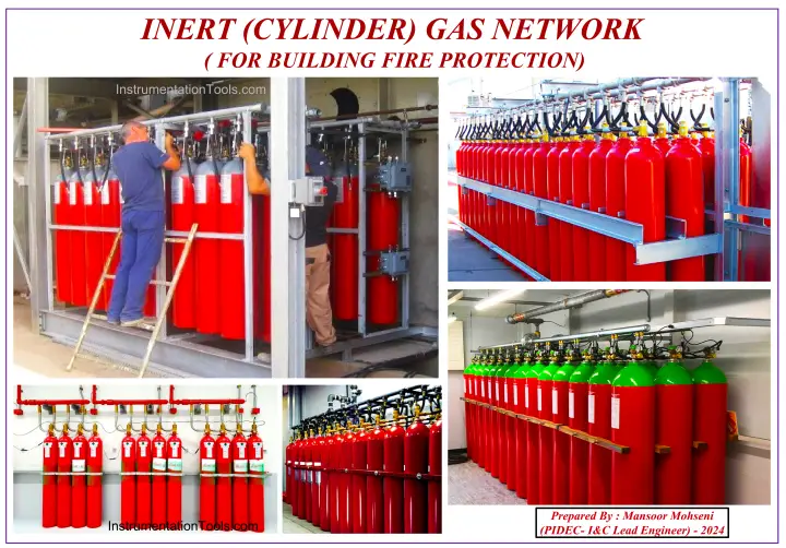
Figure-13: INERT (CYLINDER) GAS NETWORK (by SAFETY-TEAM).
Flame and Toxic Gas Detectors
For the detection of Toxic and Flammable Gas Leaks (or possible existences), and also Flame or Dangerous Heat (which may cause fire or explosion), SAFETY-TEAM shall study the plant layout in detail and locate the detectors at suitable locations (see Figure-10).
This allocation usually is done based on “Fire and Gas Detection Design Specification” which shall be provided by SAFETY-TEAM.
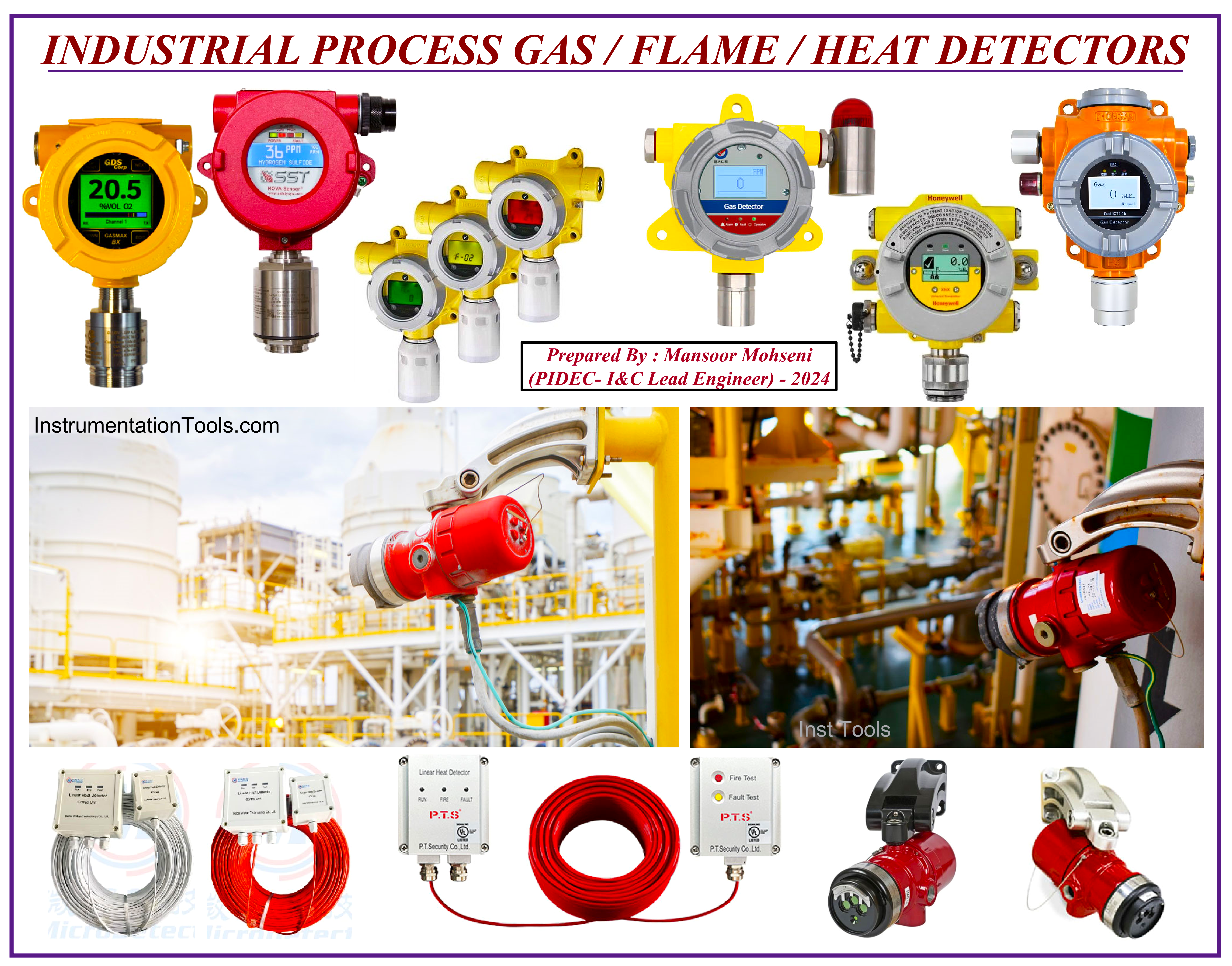
Figure-14: Industrial Process (Toxic) Gas/ Flame/ Heat Detectors.
Based on the provided layouts and relevant specifications, instrument (I&C) and electrical (EL) Teams shall assist in completing the required Datasheets and purchasing such Detectors (see Figure -14).
Usually, the provided requisition for such detectors includes other items relevant to the Fire & Gas System, including Manual Alarm Call-points (MAC), Sounders, Flashers / Beacons…
Fire and Gas (Protection) System
SAFETY-TEAM shall issue the “Fire Protection Design Specification” at the beginning of the project and then the “Fire & GAS System Design Specification” shall be issued (maybe by other disciplines like I&C). In some companies instead of two mentioned documents, one merged document is issued.
However, the I&C-Team shall incorporate purchasing a Fire & Gas System (F&G System or FGS) in accordance with the considered Process Control (Systems) Philosophy and required interfaces and safety/ control functions.
Usually, FGS is considered as one dedicated system, while in some projects (due to client request or company practices) it may be part of the Safety System (SIS) or even part of the Integrated Control & Safety System (ICSS).
Usually for fire Protection of Buildings, Local fire Alarm Systems are considered which will have some interface connection to the main F&G System. As Figure-15 shows Fire Alarm System may be designed and prepared based on Conventional items or Addressable Items.
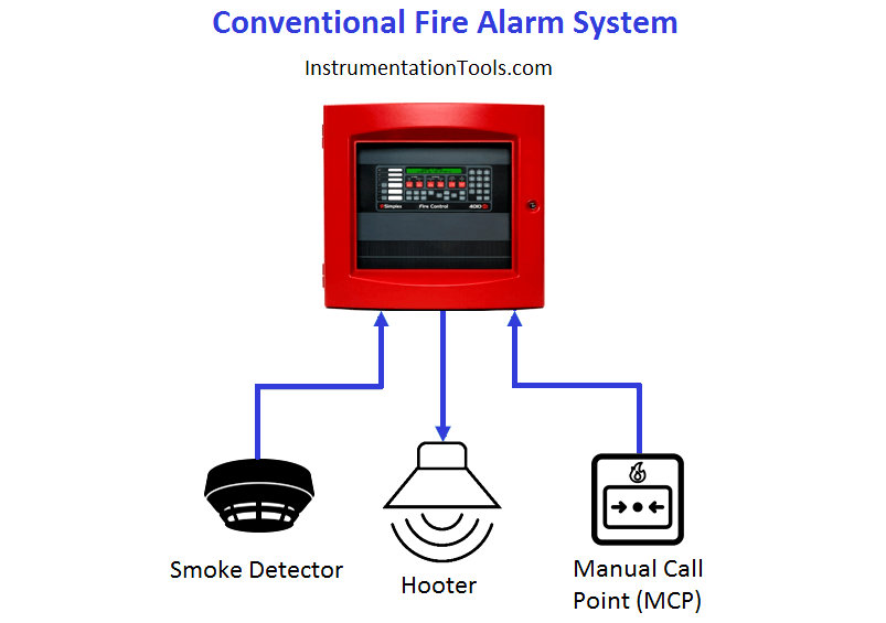
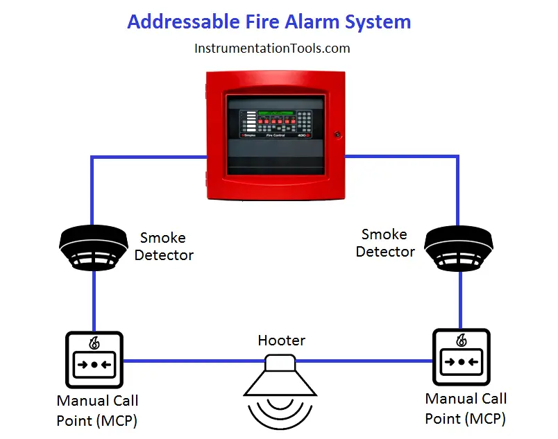
Figure-15: Conventional & Addressable Fire Alarm System.
FGS Safety & Control Functions
For implementing FGS Safety & Control Functions (maybe with the assistance of I&C-TEAM) required actions are to be defined by the “Cause & Effects Matrix” document which shall be provided by SAFETY-TEAM.
However further to this document may be a complementary document as “Control/ Safety Description (Design Basis)” shall be issued by SAFETY-TEAM.
FGS Consoles
I&C-TEAM shall incorporate for provision and configuration (/arrangement) of required consoles and operator (hardwired) panels based on project requirements via close coordination with SAFETY-TEAM.
Such consoles may include Operator Station(s), Engineering Station, Hardwired Console(s), Alarm Annunciator(s), MIMIC Panels, Wall Mounted Monitors (Large Screen), etc.
Furthermore, the I&C-Team shall incorporate for required spaces in the CCR (Control Room) for FGS panels and consoles.
Mimic Panel/ Hmi Graphic Displays
Industrial Process Projects may have some requirements for the installation of MIMIC Panels (see Figure-16) or Large Screen Monitors (Further to/ instead of MIMIC Panel). In any case, the I&C team shall assist with the implementation of them.
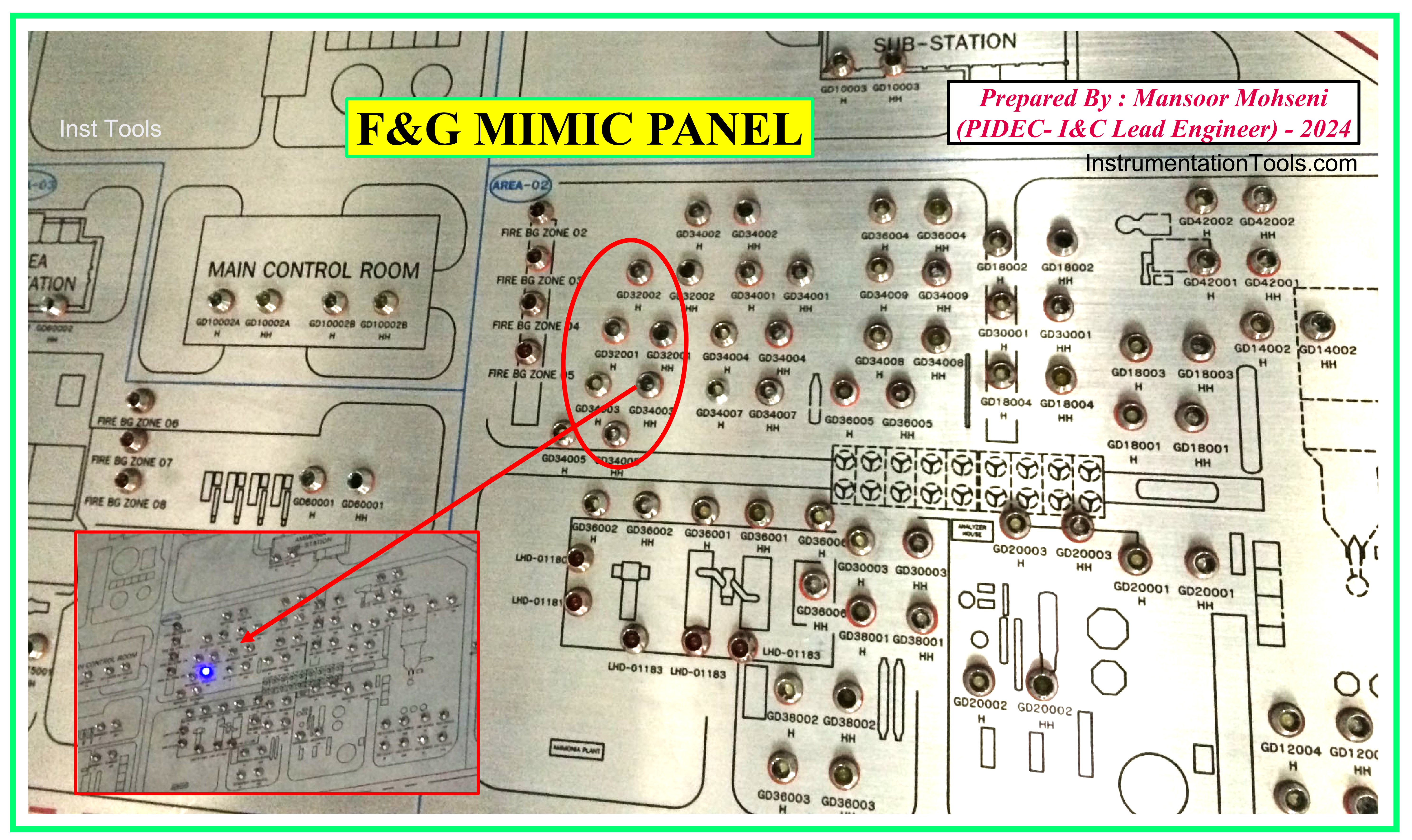
Figure-16: Sample of F&G MIMIC Panel.
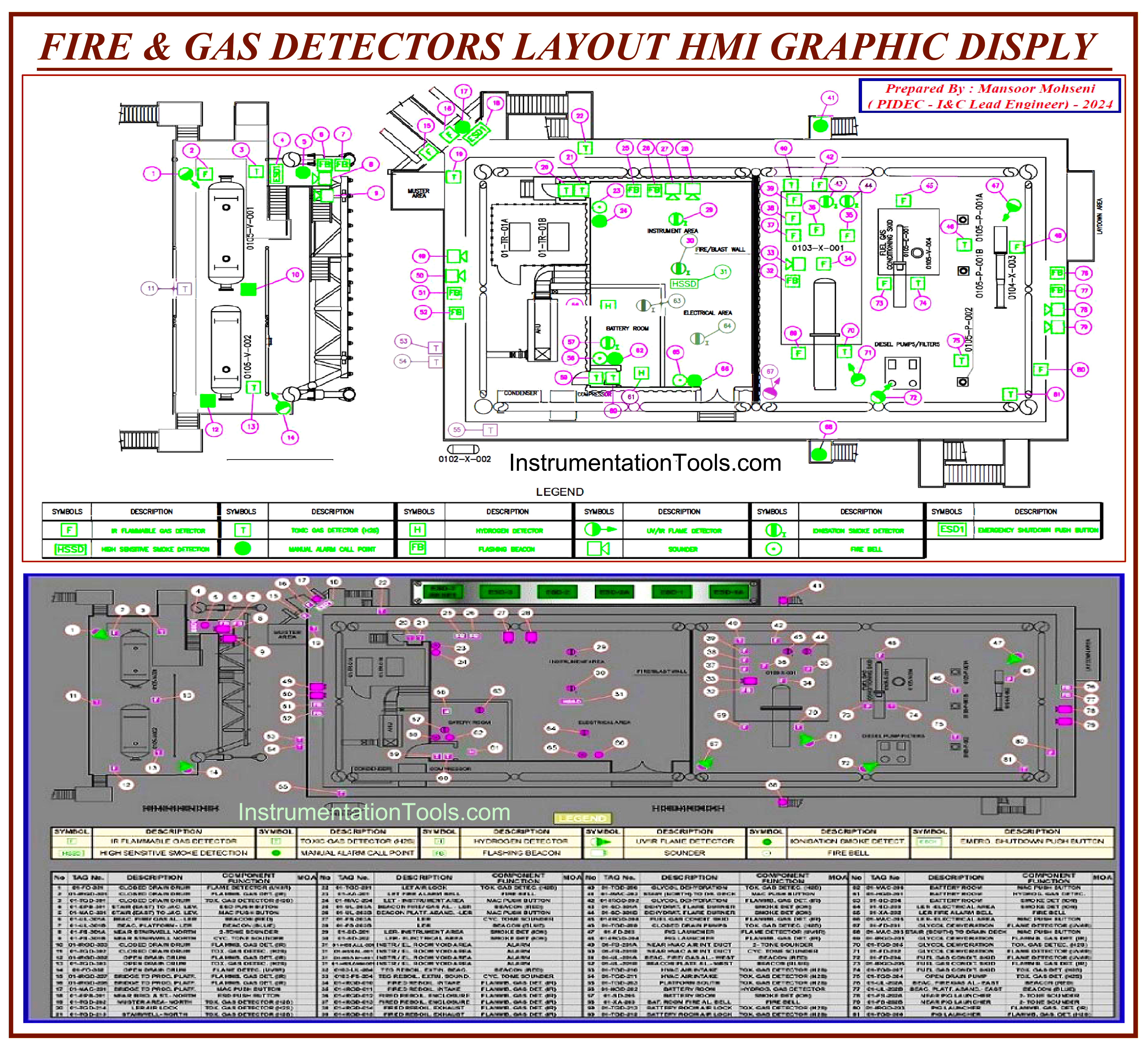
Figure-17: HMI Graphic Display for Fire & Gas (F&G) Detectors Layout.
Further to MIMIC Panel (or Large Screen Monitors) usually F&G Detectors Layout shall be monitored on DCS (Control System) HMI Monitors too (see Figure-17). This facility may be produced by some serial links (MODBUS as an example) or by direct system network data exchange (in ICSS).
For the right implementation of such HMI Graphic Displays, I&C-Team shall use F&G Detector Layout documents further to close coordination with SAFETY-TEAM.
Conclusion
Due to the close relationship between Process Engineering and Process Safety Requirements, SAFEY-TEAM may be arranged by separate Process Engineers or such team may be part of Process Engineering Team. In this manner, the title of this article is selected as “Safety Roles & Responsibilities of Process Engineering”.
We have reviewed generally some of the main activities of SAFETY-TEAM which are focused on Process Engineering (and especially have some relation with the I&C-Team).
However, it should be strictly mentioned that SAFETY-TEAM roles and responsibilities are not limited to those mentioned above and they may be more and more due to Detail Engineering Company Charts (and practices) and also the type and size of Industrial Process Plant.
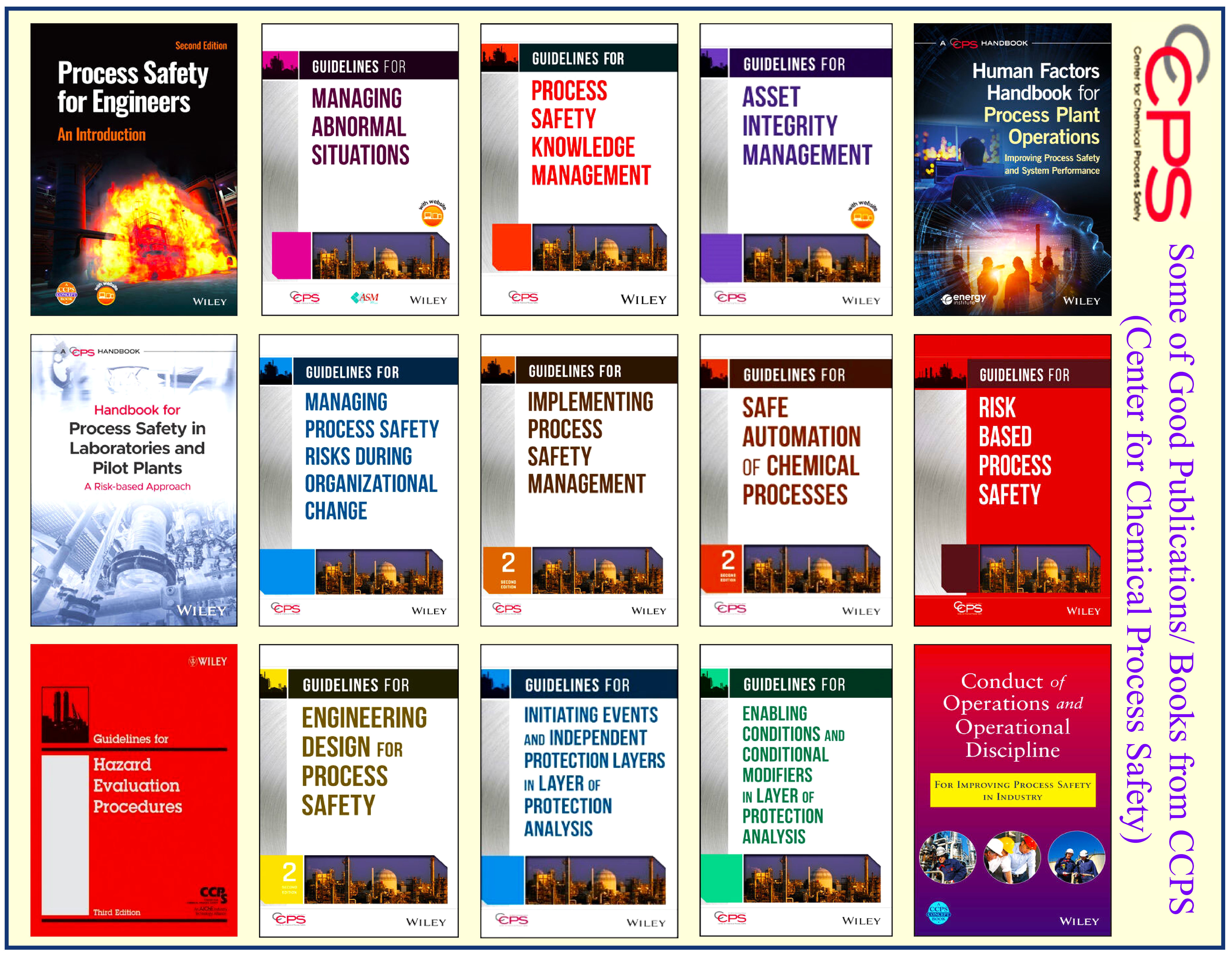
Figure-18: Some of the Good Publications/ Books from CCPS.
Safety is an important consideration (concept) in Industrial Process Plant Design and it is related to all activities and functions, Hence CCPS (Center for Chemical Process Safety) and AIChE (American Institute of Chemical Engineers) have published many good books and publication guides which some of them can be seen in Figure-18 (and are good references for PROCESS PLANT SAFETY).
References:
- Process Engineering Roles & Responsibilities
- I&C and Process Teams in Detail Design Engineering
- I&C Engineer Roles & Responsibilities – Instrumentation Design
- Instrumentation Engineer Activities & Documents