Industrial process facilities consist of a wide variety of pneumatically operated equipment which needs to be provided with a motive force for operation. Towards this, ambient air is one of the commonly used motive fluids to operate.
In an Oil & Gas project, the primary step is to assess the number of elements that need instrument air (IA) and capacities of each element (e.g., Control valve) to determine the required instrument air system capacity.
The following article focuses on sizing an IA air receiver vessel as well as some of the design considerations to made for an IA system.
Typical Layout & Operation of Instrument Air (IA) System
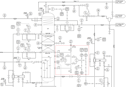
A typical layout of an Instrument Air system is shown below,
 System")
Figure 1. Schematic of Compression System
The main components of an instrument air system consist of
Inlet Air Filter
An inlet air filter to decontaminate the atmospheric air of dust and debris.
Air Compressor
An air compressor to produce instrument air at the required pressure.
Cooler
A cooler to cool the hot air from the compressor discharge.
Moisture Separator
A moisture separator to remove any condensates from the compressed air.
Air Receiver
An air receiver that stores the compressed air, a set of molecular sieve air dryers that act as a desiccant to dry the instrument air to the required dew point.
Air Dryer
Air dryers are operated in cycles whereby when one dryer is under operation, the other dryer is regenerated by removing water vapour using a pressure swing adsorption (PSA) process.
Instrument Air (IA) Receiver Design Considerations
A key component of the Instrument Air System is the Air Receiving Vessel.
The IA Receiver when designed must consider the following factors
1. Minimize Pressure Fluctuations
To meet IA consumers’ demands and during emergency shutdown scenarios, it becomes a necessity to reduce pressure fluctuations. This also means that sufficient pressure at a steady rate must always be available for processes that use IA and is measured in units of time (minutes).
2. Short Term Air Demand
In process facilities often the demand for instrument air (IA) can fluctuate sometimes reaching a peak.
This needs to be accounted for in the air compressor capacity estimates along with sufficient storage volume in the associated IA receiver to accommodate the peak demand IA flow rates.
3. Energy Savings
Instrument Air Systems run frequently consuming power & it becomes imperative to achieve power savings by operating (loading/unloading) the air compressor only as and when required.
When the pressure in the IA Receiver drops below a threshold, the IA compressor is loaded to achieve the required pressure in the IA Receiver. Sizing the IA Receiver for longer cycles enables to cut own on power consumption while providing a steady flow of IA to the end users.
Instrument Air Quality Standards
A commonly used industry standard to set instrument air quality standards is the ANSI/ISA – S7.0.01-1996. As per the described standard,
1. Pressure Dew Point
Pressure dew point is defined as the temperature at which free moisture condenses out from the instrument air into liquid water for a specific pressure.
Pressure dew point at the air dryer outlet should be at least 10 °C (18°F) below the minimum temperature to which any part of the IA system is exposed and also shall not exceed 4 °C (39°F) at the line pressure.
2. Particle Size
The IA supplied to consumers is expected to contain particulate matter and for most pneumatically operated devices, a particulate size of 40µm is acceptable.
In cases where, particulate size of < 40µm is required, additional air filtration modules can be installed to achieve < 40µm sized particulate matter.
3. Lubricant Content
In cases where the installed Air compressor in the IA system is lubricated with lube oil, there is always a risk of oil carry over along with the compressed air.
This poses a threat to the pneumatic devices that receive the instrument air and affects their operation. Hence the lubricant content should be close to 0 ppm but cannot exceed 1 ppm w/w.
4. IA System Location
The location of the Instrument Air system is also important to prevent contaminants, hazardous and flammable gases from being drawn into the Inlet air filters.
Instrument Air System Design
To evaluate the process data of an instrument air unit, a example case study is used to explain.
An Instrument air package is to be designed to deliver 600 ACFM of dry air at 8 barg to pneumatic device users. The ambient location is 20°C, with a relative humidity (RH) of 60%. The barometric pressure is 1.01325 bara.
The IA delivered to the IA receiver is required to be ~30 °C. The IA Receiver is charged/discharged through a 10 sec cycle & the operating pressure band between lower and upper pressure of the IA vessel is 10 psi.
From Steam Tables, moisture content in free air is as follows,
Table 1. Mass of H2O in Air (kg.H2O/m3 Free Sat. Air)

Water Condensation in IA Receiver
To estimate the amount of water that condenses in the wet air IA Receiver, the mass of water in air at 100% RH is taken from Table 1.
1. Water Content in saturated air [100% RH] entering compressor [0 barg] = 0.018 kg H2O/m3
2. Water Content in IA compressor suction at 60% RH = RH x Water Content at 100% RH = 0.6 x 0.018 = 0.0108 kg H2O/m3 Air
3. Water Content at IA Comp. Discharge [100% RH] at 8 barg = 0.00341 kg H2O/m3 Air [Table 1]
4. Water extracted from compressed air discharge 3 and drained via IA Receiver Liquid Outlet = 0.0108 – 0.00341 = 0.00739 kg H2O/m3
5. Water drain rate in IA Wet Receiver = 0.00739 x (600 x 0.0283168) x 60 = 7.5 kg. H2O/h
6. Relative Humidity [RH] of Air Leaving the IA Receiver to Air Dryer = 0.00341/0.018 = 19%
Pressure Dew Point in IA Inlet & IA Receiver
The pressure dew point of the instrument air processed at the IA compressor inlet and IA Receiver Exit can be calculated using Arden-Buck equation as follows.

Where,
Constant ‘b’ = 18.678
Constant ‘c’ = 257.14 °C
Constant ‘d’ = 234.50 °C
RH = Relative Humidity
Therefore, the pressure dew point at IA Compressor Inlet is,

The pressure dew point at the air leaving the IA Receiver is computed as,

Instrument Air Receiver Size
The Instrument Air Receiver which collects the compressed gas is sized based on the principle of excess pressure in the IA receiver volume in which the quantity of stored compressed air is above the facility’s requirements.
Using the actual volume flow rate flowing into the IA Receiver, the storage volume, taking into account the time cycle for charging/discharging, pressure band & barometric pressure, can be computed as,

Where,
Qc = Instrument Air Capacity [ACFM]
f = Charge/Discharge per IA Receiver Cycle [sec]
PU–PL = Pressure band of IA Receiver [psia]
Pa = Barometric Pressure at Location [psia]
Therefore, the volume of the IA receiver is computed as,

Instrument Air Dew Point at Atmospheric Pressure
The performance guarantee parameter for most industrial IA systems is based on a typical dew point requirement of -40 °C at atmospheric pressure at the outlet of the air dryer.
In the current undertaking, no calculations are shown for air dryer unit, however taking the IA receiver process conditions, it can be estimated, what should be the air dryer’s pressure dew point (i.e., at 8 barg) to achieve a performance guarantee dew point of -40 °C at 1 atm at the air dryer outlet.
To estimate the dew point at atmospheric pressure, the following dew point graph between atmospheric pressure & indicated pressure is used.

Figure 2. Air Dew Point Conversion Chart
From Fig. 2, for a pressure dew point of 3.8°C at 8 barg in IA Receiver, the dew point at 1 atm is -29°C.
Therefore for achieving an atmospheric dew point of -40°C at the air dryer outlet, the pressure dew point temperature should be -14°C at the air dryer outlet.
To estimate the relative humidity [RH] at air dryer outlet for an atmospheric dew point of -40°C,
Eq. (1) and Eq. (2) can be re-arranged as,
![Relative Humidity [RH] at Air Dryer Outlet](https://instrumentationtools.com/wp-content/uploads/2019/08/Relative-Humidity-RH-at-Air-Dryer-Outlet.png "Relative Humidity [RH] at Air Dryer Outlet")
Assuming the temperature rise in the air dryer is 40°C, the RH of the IA exiting the air dryer is,

Table 2. IA System Results Summary

Instrument Air System Design Considerations
In process facilities, it is prudent to install IA systems with a 1 Working + 1 Standby configuration. The standby Instrument Air (IA) system can be diesel driven or steam driven, subjected to the utility available.
For most utility applications, nominal instrument air line pressure for the utility industry should be ~690 kPa (100 psi). Since most industrial facilities operate with IA air at about 7 barg to 8 barg, the set pressure of the relief valve (RV) must be set higher accordingly but must not exceed the vessel design pressure.
The IA distribution lines must be sized such that the line pressure drop is not more than 1 bar between the air dryer outlet and the farthest user of IA. Typically, a user can be considered to use 0.015 m3 (0.5 SCF) of air per minute.
Air dryer regeneration methods are of two types –
- Air purge regeneration
- Heater regeneration.
Air purge regeneration
Air purge regeneration is a commonly used method where the packed column of molecular sieves is dried by diverting a fraction of the dry air from the active air dryer vessel enabling adsorption of the moisture and expelling via a purge line.
Heater regeneration
Whereas in heater regeneration methods, a heater-blower setup is installed in the regeneration line that heats ambient air & routes the heated air through the regenerating dryer. The hot air heats the regenerated dryer till the moisture reaches boiling point and is subsequently expelled through the purge line.
The regeneration time of each air dryer shall not be more than 6 hours as per IPS–G-IN-200(2). The recommended cycle time between regeneration cycles for normal operation is 6 hours for regeneration and 2 hours of standby.
The maximum allowable cycle time between regeneration cycles is 6 hours for regeneration and 4 hours standby. Hence the air dryers must be designed to be capable of drying for at least 10 hours without increase in dew point.
The air dryer adsorption operation is exothermic & causes the dried air to reach as high as 60°C. If its temperature is not expected to cool to ~40°C, additional after-coolers would be required at the air dryer outlet.
After coolers can be air-cooled type or water- cooled type. Water-cooled after coolers are usually sized to cool outlet air to within ~5°C to 8°C of the inlet cooling water temperature. Whereas Air-cooled after coolers are usually sized to cool outlet air to within 14°C to 17°C of the ambient air temperature
Compression increases the partial pressure of the water vapour present. If the water vapour partial pressure is increased to the saturation water vapour pressure, condensation occurs. If the saturation water vapour pressure is reduced to the partial pressure of the water vapour present, water or ice will result.
Therefore, moisture removal is a major consideration of instrument air treatment systems. Water droplets entrained in the air can initiate the formation of rust or other corrosion products which block internal passageways of electric to pneumatic converters resulting in sticking and/or binding of moving parts. Water droplets can also obstruct the discharge ports on solenoid air pilot valves thus reducing their ability to function properly.
Therefore an automatic drain (e.g., timer drain, float drain or an electronic drain) with a manual bypass should be located near the bottom of the air receiver to dispose of the condensate.
In cold climates, water extracted from the atmospheric air accumulates at the low points in the IA system. Hence, in such cold climates, insulation and steam tracing should be provided to both piping as well as up to a sufficient height from the bottom portion of the air receiver.
For the design and construction of the vessels, ASME Boiler and Pressure Vessel Code, Section VIII, Div. 1 or any other approved standard of equivalent authority is acceptable. For design, fabrication, erection and testing of piping ASME B16.5 and ASME B31.3 are acceptable.
In IA distribution systems, commonly used types of valves are globe valves, gate valves & ball valves. Globe valves provide the advantage of regulating system flow rates & provide tight shut-off.
On the down side, they cause reduced flow rates, increased pressure loss, and allow places for particulates to collect causing valve leakages. Gate valves & Globe valves are used for On/Off isolation & provide full, line-size port for air flow with minimal pressure drop and are conducive to internal cleaning.
The disadvantages of gate valves are that they allow particulates to collect in disc guides, and valve discs can separate from their stems. The disadvantage of ball valves is that they are more expensive than comparably-sized globe or gate valves, and their sealing surfaces are susceptible to leakage from particulate scoring.
ANNEXURE A:
Saturation Vapour Pressure at Dew Point & Actual Vapour Pressure
The saturation vapour pressure of air at its dew point can be calculated as,

Actual vapour pressure is, Pv = P1 x RH (17)
For air leaving IA receiver at TDP of 3.8°C & 19% RH

References
1. ANSI/ISA-7.0.01-1996, “Quality Standard for Instrument Air”, 12 Nov 1996
2. IPS-G-IN-200(2), “General Standard For th instrument Air Systems”, 2 Edition, Feb 2016
3. Engineering ToolBox, (2008), Compressed Air nd and Water Content
4. https://www.omnicalculator.com/physics/air- density
5. http://www.nationalcompressedair.com/dat/fil es/600.pdf
Author:
Vijay Sarathy holds a Master’s Degree in Chemical Engineering from Birla Institute of Technology & Science (BITS), Pilani, India and is a Chartered Engineer from the Institution of Chemical Engineers, UK. His expertise over 10 years of professional experience covers Front End Engineering, Process Dynamic Simulation and Subsea/Onshore pipeline flow assurance in the Oil and Gas industry. Vijay has worked as an Upstream Process Engineer with major conglomerates of General Electric, ENI Saipem and Shell.
Articles You May Like :
Level Transmitter Design Guide


Very good. thank you for sharing.
Very brief and clear article. Thanks Mr.Vijay.
Regards,
Parthiban,
SAIPEM.
Very articulate and to the point. Thanks Mr. Vijay.