Inst ToolsInst ToolsInst Tools
  • Courses
  • Automation
    • PLC
    • Control System
    • Safety System
    • Communication
    • Fire & Gas System
  • Instrumentation
    • Design
    • Pressure
    • Temperature
    • Flow
    • Level
    • Vibration
    • Analyzer
    • Control Valve
    • Switch
    • Calibration
    • Erection & Commissioning
  • Interview
    • Instrumentation
    • Electrical
    • Electronics
    • Practical
  • Q&A
    • Instrumentation
    • Control System
    • Electrical
    • Electronics
    • Analog Electronics
    • Digital Electronics
    • Power Electronics
    • Microprocessor
  • Request
Search
  • Books
  • Software
  • Projects
  • Process
  • Tools
  • Basics
  • Formula
  • Power Plant
  • Root Cause Analysis
  • Electrical Basics
  • Animation
  • Standards
  • 4-20 mA Course
  • Siemens PLC Course
Reading: Basic Principles of Electricity
Share
Notification Show More
Font ResizerAa
Inst ToolsInst Tools
Font ResizerAa
  • Courses
  • Design
  • PLC
  • Interview
  • Control System
Search
  • Courses
  • Automation
    • PLC
    • Control System
    • Safety System
    • Communication
    • Fire & Gas System
  • Instrumentation
    • Design
    • Pressure
    • Temperature
    • Flow
    • Level
    • Vibration
    • Analyzer
    • Control Valve
    • Switch
    • Calibration
    • Erection & Commissioning
  • Interview
    • Instrumentation
    • Electrical
    • Electronics
    • Practical
  • Q&A
    • Instrumentation
    • Control System
    • Electrical
    • Electronics
    • Analog Electronics
    • Digital Electronics
    • Power Electronics
    • Microprocessor
  • Request
Follow US
All rights reserved. Reproduction in whole or in part without written permission is prohibited.
Inst Tools > Blog > Electrical Basics > Basic Principles of Electricity

Basic Principles of Electricity

Last updated: May 3, 2017 3:40 pm
Editorial Staff
Electrical Basics Instrumentation Design
No Comments
Share
3 Min Read
SHARE

Basic Principles of Electricity

Electricity

Electricity, simply put, is the flow of electric current along a conductor. This electric current takes the form of free electrons that transfer from one atom to the next. Thus, the more free electrons a material has, the better it conducts. There are three primary electrical parameters: the volt, the ampere and the ohm.

1. The Volt

The pressure that is put on free electrons that causes them to flow is known as electromotive force (EMF). The volt is the unit of pressure, i.e., the volt is the amount of electromotive force required to push a current of one ampere through a conductor with a resistance of one ohm.

2. The Ampere

The ampere defines the flow rate of electric current. For instance, when one coulomb (or 6 x 10¹⁸ electrons) flows past a given point on a conductor in one second, it is defined as a current of one ampere.

3. The Ohm

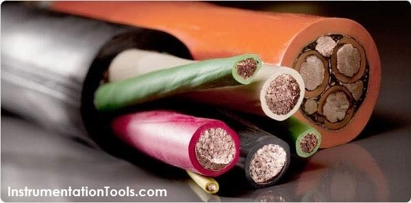
The ohm is the unit of resistance in a conductor. Three things determine the amount of resistance in a conductor: its size, its material, e.g., copper or aluminum, and its temperature. A conductor’s resistance increases as its length increases or diameter decreases. The more conductive the materials used, the lower the conductor resistance becomes. Conversely, a rise in temperature will generally increase resistance in a conductor.

Ohm’s Law

Ohm’s Law defines the correlation between electric current (I), voltage (V), and resistance (R) in a conductor.

Ohm’s Law can be expressed as: V = I × R

Where: V = volts, I = amps, R = ohms

Ampacity

Ampacity is the amount of current a conductor can handle before its temperature exceeds accepted limits. These limits are given in the National Electrical Code (NEC), the Canadian Electrical Code and in other engineering documents such as those published by the Insulated Cable Engineers Association (ICEA). It is important to know that many external factors affect the ampacity of an electrical conductor and these factors should be taken into consideration before selecting the conductor size.
Don't Miss Our Updates
Be the first to get exclusive content straight to your email.
We promise not to spam you. You can unsubscribe at any time.
Invalid email address
You've successfully subscribed !

Continue Reading

Rotary Encoder Interview Questions and Answers
Circuit Breaker Making Capacity
Multiple Thermowell Installations Problems
What is Inter Discipline Check (IDC)?
Difference Between Electric Field and Magnetic Field
Heat Tracing Problems
Share This Article
Facebook Whatsapp Whatsapp LinkedIn Copy Link
Share
Leave a Comment

Leave a Reply Cancel reply

Your email address will not be published. Required fields are marked *

Stay Connected

128.3kFollowersLike
69.1kFollowersFollow
210kSubscribersSubscribe
38kFollowersFollow

Categories

Explore More

Types of Circuit Breakers, Advantages, Disadvantages
Difference between Stepper Motor and DC Motor
Difference Between Normal Inverter and Solar Inverter
Thermowell Design Guidelines
What is a Buchholz Relay? Working Principle
Ferrules and Cross Ferruling
How to Read and Understand an Electrical Single Line Diagram?
What is SMPS? – Types of SMPS

Keep Learning

Types of Batteries

Cells and Batteries – Types, Applications, Explanation

Earth Fault

What are Ground Fault and Earth Fault?

Marshalling Panel

What is Marshalling Cabinet?

Electric Motors Noises

Electric Motors Noises – Types, Possible Sources, Reasons

Types of Motor Enclosures

Types of Motor Enclosures

Three-Phase Power Supply

Single Phase versus Three Phase Power

Control System Vendor Internal Test Procedures

Vendor View of Supplying Industrial Process Control & Safety Systems

Control systems in industrial projects

Interactions With Process Control Systems Philosophy

Learn More

Practical Control Systems Questions & Answers

Practical Process Control System Questions & Answers – 3

Capacitance Level measurement principle

Capacitance Level Sensor Principle, Limitations, Installation & Calibration

Garage Door Roller Shutter

Shutter Door Control using Motor and Limit Switches

Electrical Feeder Automation in Smart Grid

Electrical Feeder Automation in Smart Grid

Optimal Control Systems

Output Regulator & the Tracking Problem

Parts of PLC

Parts of PLC

Sheet Metal Fabrication Manufacturing and Design

Ideal Guide To Sheet Metal Fabrication Manufacturing and Design

What is a Fotonic Sensor

What is a Fotonic Sensor? – Working Principle, Advantages, Disadvantages

Menu

  • About
  • Privacy Policy
  • Copyright

Quick Links

  • Learn PLC
  • Helping Hand
  • Part Time Job

YouTube Subscribe

Follow US
All rights reserved. Reproduction in whole or in part without written permission is prohibited.
Welcome Back!

Sign in to your account

Username or Email Address
Password

Lost your password?