Inst ToolsInst ToolsInst Tools
  • Courses
  • Automation
    • PLC
    • Control System
    • Safety System
    • Communication
    • Fire & Gas System
  • Instrumentation
    • Design
    • Pressure
    • Temperature
    • Flow
    • Level
    • Vibration
    • Analyzer
    • Control Valve
    • Switch
    • Calibration
    • Erection & Commissioning
  • Interview
    • Instrumentation
    • Electrical
    • Electronics
    • Practical
  • Q&A
    • Instrumentation
    • Control System
    • Electrical
    • Electronics
    • Analog Electronics
    • Digital Electronics
    • Power Electronics
    • Microprocessor
  • Request
Search
  • Books
  • Software
  • Projects
  • Process
  • Tools
  • Basics
  • Formula
  • Power Plant
  • Root Cause Analysis
  • Electrical Basics
  • Animation
  • Standards
  • 4-20 mA Course
  • Siemens PLC Course
Reading: Float-type Level Switch to Control a pump
Share
Notification Show More
Font ResizerAa
Inst ToolsInst Tools
Font ResizerAa
  • Courses
  • Design
  • PLC
  • Interview
  • Control System
Search
  • Courses
  • Automation
    • PLC
    • Control System
    • Safety System
    • Communication
    • Fire & Gas System
  • Instrumentation
    • Design
    • Pressure
    • Temperature
    • Flow
    • Level
    • Vibration
    • Analyzer
    • Control Valve
    • Switch
    • Calibration
    • Erection & Commissioning
  • Interview
    • Instrumentation
    • Electrical
    • Electronics
    • Practical
  • Q&A
    • Instrumentation
    • Control System
    • Electrical
    • Electronics
    • Analog Electronics
    • Digital Electronics
    • Power Electronics
    • Microprocessor
  • Request
Follow US
All rights reserved. Reproduction in whole or in part without written permission is prohibited.
Inst Tools > Blog > Instrumentation Design > Float-type Level Switch to Control a pump

Float-type Level Switch to Control a pump

Last updated: October 30, 2019 12:36 pm
Editorial Staff
Instrumentation Design Practical Questions
No Comments
Share
1 Min Read
SHARE

Sketch the necessary wiring to make this float-type level switch control a pump and a lamp in the following manner:

  • High liquid level: pump on and lamp off
  • Low liquid level: pump off and lamp on
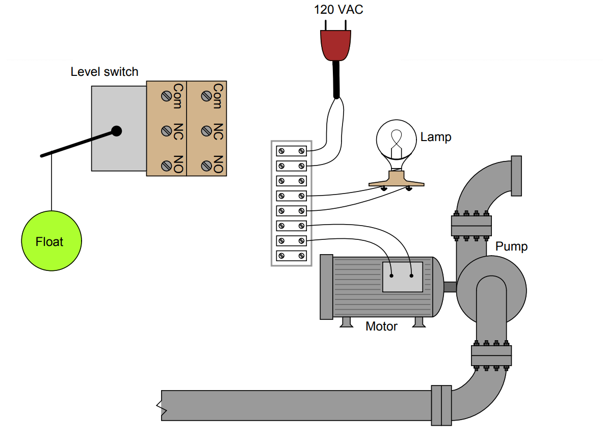
float-type level switch

Hint: remember that the “normal” status of a switch is defined as the status of minimum stimulus: when the switch is exposed to the lowest possible degree of process stimulation (in this particular case, to the lowest possible level).

Answer : 

This is just one possible solution:
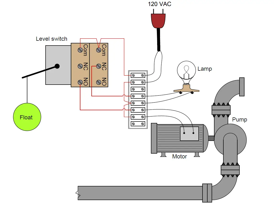
float-type level switch control a pump

Share Your Answer / Comments

Credits : by Tony R. Kuphaldt – under CC BY 1.0
Don't Miss Our Updates
Be the first to get exclusive content straight to your email.
We promise not to spam you. You can unsubscribe at any time.
Invalid email address
You've successfully subscribed !

Continue Reading

Redundant Power Supply for Critical Field Panels
Pneumatic Force Balance Instrument
Analytical Control System of Heat Exchanger Questions
How to Select the Right Panel Enclosure for Your Application?
Oil and Air Pressure Actuated Lifts Questions
Detail Design Engineering Competency Aspects
Share This Article
Facebook Whatsapp Whatsapp LinkedIn Copy Link
Share
Leave a Comment

Leave a Reply Cancel reply

Your email address will not be published. Required fields are marked *

Stay Connected

128.3kFollowersLike
69.1kFollowersFollow
210kSubscribersSubscribe
38kFollowersFollow

Categories

Explore More

Instrument Air Sizing
Pneumatic Level Transmitter Calibration Table
How to Select a Pressure Gauge
Paint Mixing System
How to Minimize Water Vapor in Instrument Air Lines?
What Affect the Pressure Measurement Accuracy of a Manometer?
Instrument Protection Methods: Seals
Heat Exchanger Differential Pressure Transmitter

Keep Learning

Switch Contact checking with oscilloscope

What is Contact bounce ?

Thermowell Problems

Thermowell Problems

Instrumentation Transmitter

Instrumentation Common Measurement Issues

NACE Standards - MR0103 Vs MR0175

NACE Standards – MR0103 Vs MR0175

Control Room Design Guidelines

Control Room Design Guidelines

Signal Strength of Guided-wave Radar Level Instrument

Signal Strength of Guided-wave Radar Level Instrument

Remote Seals Transmitters Temperature Error

Remote Seal Transmitters Temperature Error

Problem on Tachogenerator

Problem on Tachogenerator

Learn More

Marshalling Panel

What is Marshalling Cabinet?

Solid State Relay Working Principle

What is a Solid State Relay? – Working Principle, Types of Control

State Variable Analysis and Design

Solution of State Equations

Solenoid-controlled Valve Problem

Solenoid-controlled Valve Problem

Power Electronics Objective Questions

Thyristor Firing Objective Questions

Electric Motors Efficiency Classes

Electric Motors Efficiency Classes

Electrical Machines Objective Questions

Electrical Machines MCQ Series 7

Distributed Control System Architecture for Profibus Field Instruments

H1 FF Physical layer

Menu

  • About
  • Privacy Policy
  • Copyright

Quick Links

  • Learn PLC
  • Helping Hand
  • Part Time Job

YouTube Subscribe

Follow US
All rights reserved. Reproduction in whole or in part without written permission is prohibited.
Welcome Back!

Sign in to your account

Username or Email Address
Password

Lost your password?