Complete and accurate documentation is critical to the commissioning and ongoing maintenance and operation of a PLC or DCS system and should be a high priority of design contract administration.
PLC or DCS system documentation provided by the system designer and/or system integrator should include the following:
- One-line diagrams
- Piping and instrumentation diagrams (P&IDs)
- Sequences of operation
- Instrument data sheets
- Points list
- Loop diagrams or I/O wiring diagrams
- Binary logic diagrams
- Control schematics
- PLC / DCS program listing
- HMI description (screenprints and database)
- Software configuration management documentation
- Facility physical and information security policies
All PLC or DCS documentation should be furnished in both hard copy and appropriate electronic format. The electronic format should be capable of revision; i.e. scanned documents or portable document format (pdf) files are not acceptable, although pdfs may be submitted as archive copies in addition to revisable files.
All system documentation should be treated as sensitive and this applies to PLC or DCS system diagrams and documentation as well. At a minimum, document security measures should include:
- Marking all documents
- Controlling access to documents
- Properly destroying outdated or unused documents
Symbols and identification
Individual control loops should be identified by loop number following the convention established by ISA S5.1.
Each instrument, actuator and control point should have a unique tag number incorporating the loop number and identification letters per table 1 of ISA S5.1. All equipment and instruments should be consistently identified by their complete tag number on all drawings and points lists.
Piping and Instrumentation Diagram (P&ID)
P&IDs should be provided for all mechanical systems. P&IDs should depict all components of mechanical systems including vessels, pumps, compressors, chillers, heat exchangers, piping, valves and instruments and the control relationships between them. Symbols used should comply with ISA S5.1 – Instrumentation Symbols and Identification and ISA 5.3 – Graphic Symbols for Distributed Control/Shared Display Instrumentation, Logic and Computer Systems.
Sequences of operation
Written sequences of operation should be provided for all control loops.
Sequences of operation should include the following minimum information:
- Manual and automatic control modes;
- Normal system conditions and modes of operation;
- Contingency conditions and modes of operation;
- Effect of all operator controls;
- Description of all interlocks and permissives;
- Identification of failure state of all outputs.
Instrument data sheets
Instrument data sheets should be provided per ISA S20
Check the following instrumentation checklists:
- Transmitter Loop Checklist
- Process Switches Checklist
- PID Controller Checklist
- PLC Digital Input Checklist
- Instrument Installation Checklist
Points list
A points list should be provided that includes all real and virtual input, output and control points.
Provide the following information, where applicable, for each point:
- System
- Equipment
- Loop number
- Tag number
- Controller, rack, and slot
- Point type
- Field location
- Range
- Failure state
Example of Point List

Loop diagrams
Loop diagrams define the physical wiring for each loop from each instrument or actuator to the controller. All field devices, terminal boards, junction boxes, etc. are depicted along with the signal type and range.
These drawings are the basis for verification of all PLC or DCS system field wiring, instrument calibration, and loop tuning. All devices, terminals, cables, and conductors must be completely identified on the loop diagrams per ISA S5.4 – Instrument Loop Diagrams.
Example of Loop Diagrams

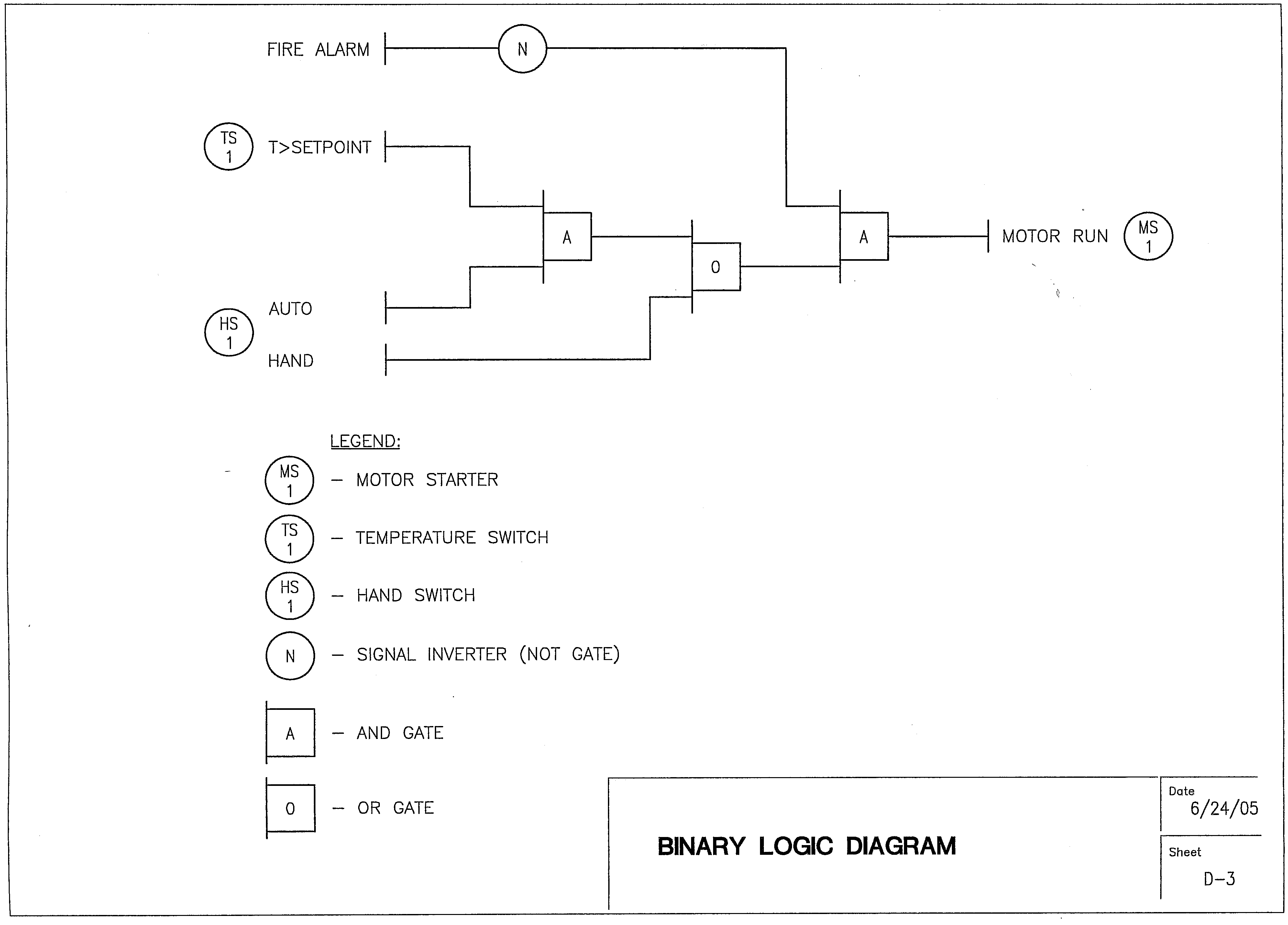
Binary Logic Diagrams
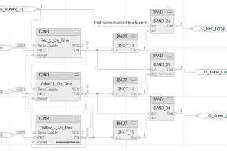
Binary logic diagrams are flowcharts that depict all discrete logic using Boolean logic symbols. Logic diagrams should comply with ISA S5.3 – Binary Logic Diagrams.
Example of Logic Diagram
Control Schematics
Control schematics show the interface between the PLC or DCS system and the internal wiring of related equipment such as field instruments, motor starters, pump control panels, generator control panels, etc.
Proper development of control schematics requires a significant effort on the part of the PLC or DCS system integrator because the standard drawings provided by manufacturers of these related system drawings are typically inconsistent in format, symbols and content, requiring that they be redrafted by the integrator to provide an integrated documentation package. Symbols used on control schematics should comply with the previously referenced ISA standards and ANSI Y14.15. – Electrical and Electronic Diagrams.
Example of Control Schematics

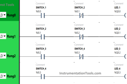
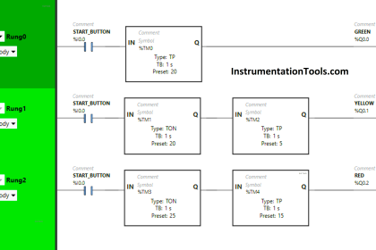
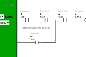
PLC / DCS program listing
A documented listing of the complete program of each PLC / DCS should be provided. Documentation should consist of an English-language description of the function of each logic rung inserted into the listing.
The below list shows some of the documents.
- Instrument Hook-up Drawings
- Logic Checks Drawings
- Loop Checks Drawings
- Instrument Functional Diagrams
- Piping & Instrumentation (P&ID)
- Process Flow Diagrams (PFD)
Change Control
All PLC or DCS documentation should include creation date, issue date, revision data, and revision history in a format that is consistent across all documents. A document database or spreadsheet should be maintained that provides a current listing of all documents and their revision status.
The database should include the following:
- Document Type
- Document Number
- Page Number
- Sheet Number
- Title
- Current Revision
- Revision Date
Each submittal of PLC or DCS documentation should include an updated submittal of the document database. The database should be provided in electronic format and maintained on an ongoing basis by the facility manager after system commissioning. All changes made to the system should be promptly reflected by revising the documentation and the database and distributing copies of the revised documentation and updated database to the field.
Join the Discussion
Share & leave us some comments on what you think about this topic or if you like to add something.
Reference: This material adapted from the “Department of the Army, TM 5-601, Supervisory Control and Data Acquisition (SCADA) Systems for Command, Control, Communications, Computer, Intelligence, Surveillance, and Reconnaissance (C4ISR) Facilities, 21 January 2006.”
If you liked this article, then please subscribe to our YouTube Channel for PLC and SCADA video tutorials.
You can also follow us on Facebook and Twitter to receive daily updates.
Read Next:
- Commissioning Documents
- Architecture of Instrumentation
- What is PID Controller?
- Alarm Management Practices
- Examples of SCADA and PLC


Hi,
Very useful documents for PLC engineers and students.
My project is how to control (Frequency, voltage, temperature, and protection) Micro hydropower generator using PLC.
Thanks