Alarm and Trip Systems
The purpose of an alarm system is to bring a malfunction to the attention of operators and maintenance personnel, whereas the purpose of a trip system is to shut down a system in an orderly fashion when a malfunction occurs, or to switch failed units over to standby units. The elements used in the process control system are the first warnings of a failure. This could show up as an inconsistency in a process parameter, or as a parameter going out of its set limits.
The sensors and instruments used in the alarm and trip system are the second line of defense, and must be totally separate from those used in the process control system. Alarm and trip system information and its implementation are given in ANSI/ISA-84.01-1996—Application of Safety Instrumented Systems for the Process Control Industry.
Safety Instrumented Systems
The alarm and trip system, or Safety Instrumented System (SIS), has its own sensors, logic, and control elements, so that under failure conditions, it will take the process to a safe state to protect the personnel, facility, and environment. To ensure full functionality of the SIS, it must be regularly tested. In an extreme situation, such as with deadly chemicals, a second or third SIS system with redundancy can be used in conjunction with the first SIS system, to ensure as close to 100% protection as possible.
The sensors in the SIS usually will be of a different type than those used for process control. The control devices are used to accurately sense varying levels in the measured variable, whereas the SIS sensor is used to sense a trip point, and will be a much more reliable, rugged, and high-reliability device. The use of redundancy in a system cannot be used as a justification for low reliability and inexpensive components.
The most commonly used high performance SIS system is the dual redundancy system, which consists of the main SIS with two redundant systems. In this case, a two-out-of-three logic monitoring system determines if a single monitor or the entire system has failed. If a single failure is detected, then the probability is that a sensor, its associated wiring, or logic has failed. If more than one failure is detected, then the indication is a system failure.
A two-out-of-three logic circuit is shown in Figure (a), and the truth table is shown in Figure (b). With correct operation, the inputs are normally low (0). If one input goes high (1), it would indicate a sensor failure, and the sensor failure output would go from 0 to 1 to give warning of a sensor failure, but the system failure output would remain at 0. If two or more inputs go high, it would indicate a system failure, and the system failure out put would go from 0 to 1, as shown.
In SIS systems failure analysis, the rate of component failure is as follows:
- Logic, 8%;
- Sensors, 42%;
- Control devices, 50%.
Safe Failure of Alarm and Trip
No system is infallible, and failures are going to occur. A good philosophy is the fail-safe approach, where each valve will trip to a predetermined fail position when they are deenergized. Even with an uninterruptible power system, power wires can get cut, fuses can blow, or cables can break, cutting off power. In some cases, this approach is not feasible, and extra safeguards are necessary to maintain safety when the SIS fails.
There are typically three levels of safety, and the systems normally associated with the safety levels are:
Level 1 —Single sensor with a one-out-of-one logic detection and single final control.
Level 2 —More diagnostics than Level 1, plus redundancy for each stage.
Level 3 —Minimum of two systems with redundancy, or a two-out-of-three sensing system.
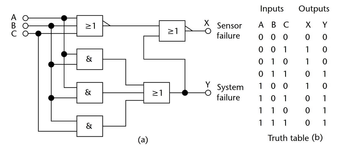
Figure (a) Monitor and two-out-of-three failure indicator, and (b) truth table.
Components in an SIS system should be high-grade, with a high mean time between failures (MTBF). Relays were the preferred choice due to the capability of multiple contacts and isolation. However, semiconductor devices have an excellent MTBF, and they are replacing relay logic. A good design will take into account the integrity of all the components in an alarm system, as well as interactions between the components.
Testing of the alarm system is required on a regular basis to uncover faults or potential failures, which require corrective action. Testing is of prime importance in SIS applications. An SIS is designed to detect hazardous conditions, so it must be able to sense a malfunction of the logic, measuring device, and final alarms during testing. The requirements and testability of the SIS must be factored in at the system design stage.


Dear Mr V. Manikanta :thanks for your article just to remind u or consider it as new addition in the place where i was working as instrument maintenance engineer we have digital control system i.e using logic circuits to detect the signal from field sensors whether it is Alarm or Shut Down,
so the design classified the type of shut down into two parts /First degree shut down and second degree, So the second degree means only Alarm with Buzzer but can be reset while first degree shut down is the real shut down for any reason such us High station pressure discharge or low suction pressure for one of the main pumps or sudden close for the main valve type MOV so on for any real type of shut down.
Here for first degree the Alarm still produces Buzzer or the annunciation working till the maintenance team solve the problem and then the operator can do reset the Alarm.
so kindly confirm this with the new DCS criteria but i;m sure all are the same despite the name first or second degree of shut down.
/George Ibraheem -Instrument Engineer
This text is from Chapter 17 of
William C. Dunn, Introduction to Instrumentation, Sensors, and Process Control, Artech House, 2006.
please check the connection on the fig (a) as AB is and gated twice instead of AC
Very true, if A and C fail the system fault will not be triggered.