From Where do we get these Numbers and What significance do they have that we must keep the Orifice Beta ratio in orifice calculation between 0.3 and 0.7 Values?
Orifice Beta Ratio
Let us start with What is BETA? Then let’s get rebellious and take “Extreme cases”!!
BETA = I.D of Orifice (BORE of Orifice) / O.D of Orifice (I.D of Pipe)

For Understanding purpose. Let’s get rebellious and take “Extreme cases”
What if we take a BETA of 1?
This is possible if I.D of orifice = O.D of Orifice
But that means There is no restriction to flow so no Pressure Drop.
And No pressure drop hence Flow measurement is not possible
What if we take a BETA of 0.9?
This is possible if the I.D of the orifice is approximately near the O.D of the Orifice
But that means There is very little restriction to flow so very little Pressure Drop.
As low-pressure drop will be difficult to measure, so we don’t go beyond 0.7
Also “UNCERTAINTY INCREASES“, this concept is explained below.

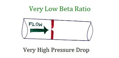
What if we take a BETA of 0.1?
This is possible if the I.D of the orifice is very small as compared to the O.D of the Orifice
But that means there is a very high restriction to flow so very High-Pressure Drop.
This is Good, Right? High-pressure drop means it will be easy to measure.
This is not the only consideration we have !!
It affects a variety of things (Here are a few reasons listed below)
Process Hydraulics
This Affects Process Hydraulic calculation and also leads to Inefficiency in the process as a whole.
As the PUMP will have to PUMP MORE !! As a result Process people in their Datasheet specify maximum allowable Pressure loss in Orifice.
What is the use of purposefully creating more restrictions and then trying to compensate it with more pumping power?
More Probability of Cavitation and Flashing
The more we drop the pressure the more the chances of liquid reaching “Vapor Pressure”
And thus more is the chances for “Cavitation and Flashing”
NEXT important consideration
Coefficient of Discharge (Uncertainty)
The estimated uncertainty of the empirical coefficient of discharge for concentric, square-edged, flange-tapped orifice meters that are in compliance with this standard (API 14.3.1) is a function of the Reynolds number and the diameter ratio (β)
i.e:- Cd (Uncertainty) is a function of Reynolds Number & Diameter ratio
( Reference API Manual of Petroleum Measurement Standards Chapter 14.3.1 PAGE NO 31)
At very high Reynolds numbers (approx. greater than 1,00000) the uncertainty is only a function of the diameter ratio (BETA) (β)
So Here’s Where Beta Ratio again comes into the picture
Below is a graph from API Standards Chapter 14.3.1 that has Percent Uncertainty Vs Beta Ratio (See Comments in Red)

So from this graph, we can deduce it is better to come to a nearby moderate value of BETA approx.=0.5 for better accuracy !!
Lastly one unanswered question?
Why only between 0.3 to 0.7
There is no hard and fast rule it is just due to the above reasons we try to stay in the moderate range, this limit is established by the “Empirical” Method (That is by experimental means, we have come to this value).
Some standards say we should be between 0.2 to 0.6
Nonetheless, stay Safe and select a moderate value
Thanks for Reading !!
PS: This is as per best of my current understanding !!
Author: Asad Shaikh
Profile: Linkedin
If you liked this article, then please subscribe to our YouTube Channel for Instrumentation, Electrical, PLC, and SCADA video tutorials.
You can also follow us on Facebook and Twitter to receive daily updates.
Read Next:
- When to use Diaphragm Seal?
- Different Types of Orifice Taps
- Selection of Flow Instruments
- Valve Relation between Cv and Kv
- Safety Instrumented System Failure


Very nicely explained, without complicating with equations