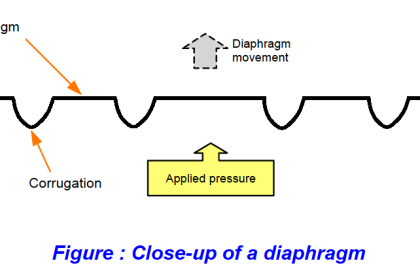
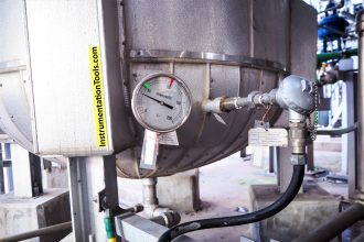
Taking a DP, gauge, or absolute pressure reading from a process involves creating process connections so the pressure can reach the sensor.
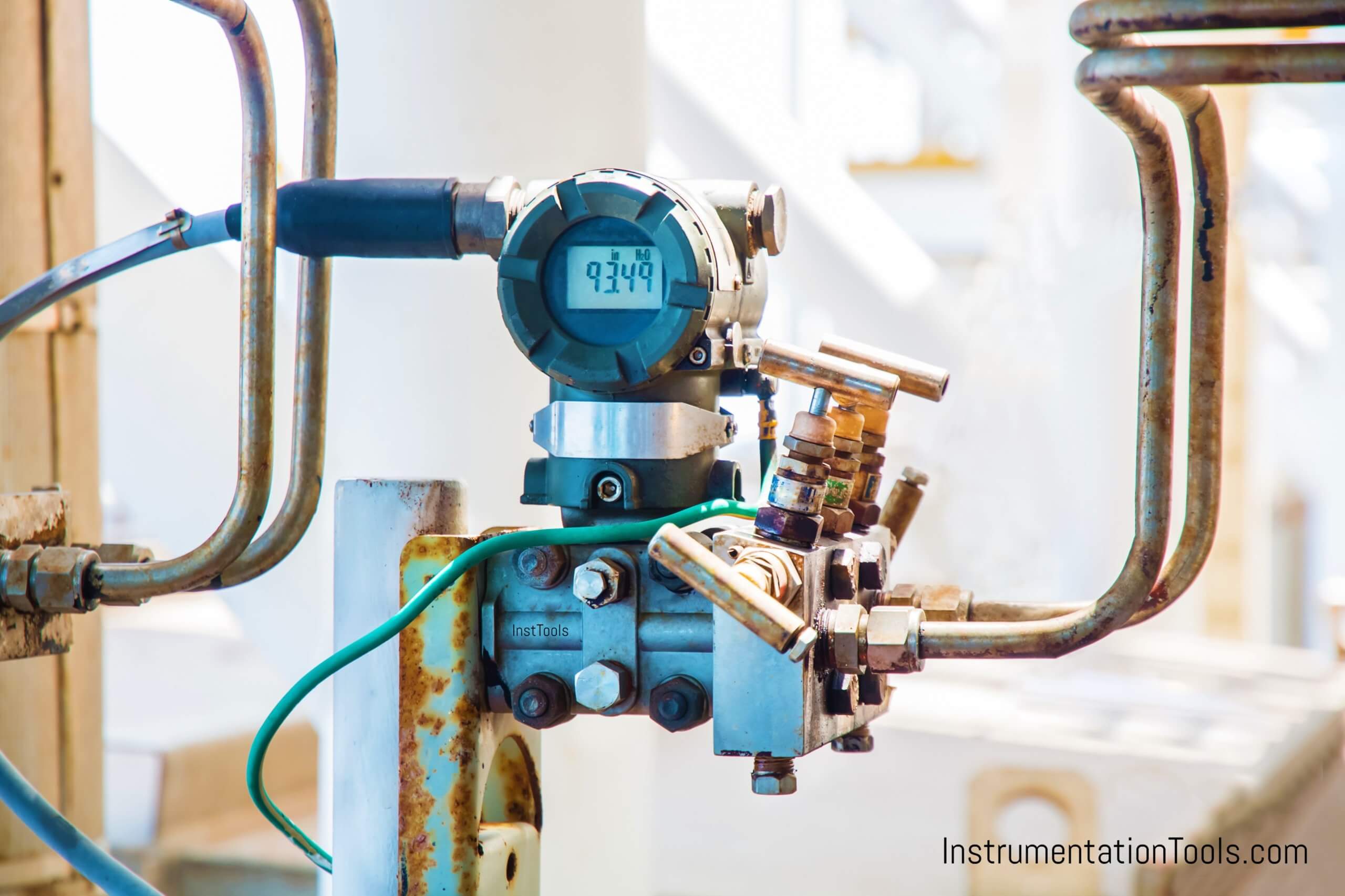
Impulse Line
Frequently this is done via impulse lines.
The impulse line carries the process pressure from the tapping point to the transmitter.
In some cases, these can be short and very direct, or they may need to be long to allow mounting the transmitter some distance from the process equipment.
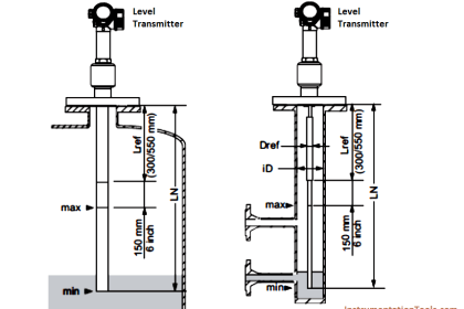
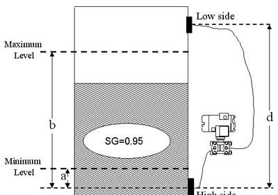
The transmitter should be installed below the process tapping points to a wall or other rigid mounting using the optional bracket assembly or similar rigid bracket.
The transmitter should be piped up in compliance with the pressure transmitter installation guidelines with the process tappings taken to the side of the pipe work.
The transmitter should be mounted within two degrees of the horizontal, small variations in mounting attitude will affect the transmitter zero point, however, this may be calibrated out during the initial commissioning procedure detailed later.
When used on steam service the transmitter and impulse lines must be filled with water before the system startup to prevent live steam from damaging the transmitter.
The transmitter should be installed above the process tapping points to a wall or other rigid mounting using the optional bracket assembly or similar rigid bracket.
The transmitter should be piped up in compliance with the pressure transmitter installation guidelines with the process tappings taken to the top of the pipework.
The transmitter is placed above the process measurement tapping to allow condensed liquid to drain back into the process lines.
The transmitter should be mounted within two degrees of the horizontal, small variations in mounting attitude will affect the transmitter zero point, however, this may be calibrated out during the initial commissioning procedure detailed later.
Problems
Conventional impulse lines can create a variety of problems:
- They are part of the process containment
- If they leak, the product is lost, with potential safety, economic, and environmental implications
- If process equipment calls for exotic materials, the impulse lines need it too
- They can fill with gas or liquid which compromise their ability to transmit pressure accurately
- They can freeze in cold weather
- Blockage
- Improper lines may cause damping of pressure signals
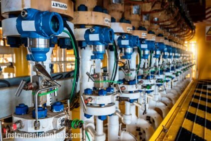
Impulse lines are typically custom efforts and often built in the plant’s maintenance shop, reflecting the skill of local contractors or pipe fitters.
Solutions
A better choice is to use a pre-assembled instrument, such as is available with a DP flow meter, a complete unit built in a factory and fully tested.
All fasteners are tightened to the optimum torque level and the finished assembly can be leak tested. These meters are ready to install right out of the box and even include a calibration report.
Whatever the situation, impulse lines must not impede pressure delivery so the transmitter can read the sensor value indicating the actual process condition.
As an extreme example, if there is an isolation valve on the impulse line and the valve is closed, nothing can reach the transmitter, and its reading will not reflect the process conditions.
Such a situation is not always easy to detect because some pressurized fluid may be trapped in the line and reflected by the transmitter.
Similarly, inaccurate readings can result when the line is partially plugged, frozen, or there is some other internal obstruction.
Today’s advanced transmitters are able to perform a plugged impulse line diagnostic and detect such situations because they listen to the process noise through the connection.
If the noise level decreases or changes character and there is no attributable cause, there is likely an obstruction forming in the lines.
Once the change crosses a designated threshold, the transmitter can warn operators and maintenance engineers.
Process intelligence capabilities can also be built into pressure transmitters, allowing them to listen to process noise continuously.
Once a baseline of normal noise is retained in the transmitter’s memory, it can perform statistical analysis on what it hears, listening for patterns deviating from normal.
Reasons for such changes can include:
- Pump cavitation
- Distillation column flooding
- Regulator and valve setting changes
- Furnace flame instability
Characterizing and analyzing such noise provides a tool to help operators or engineers identify a likely source.
Operators and maintenance engineers can be informed early so the situation can be corrected immediately if necessary or monitored until a scheduled shutdown.
Process alerts can also indicate upsets and other conditions capable of creating spikes or dips in normal readings.
Such alerts can be logged in individual transmitters and accessed during troubleshooting.
A status log can look back at the last 10 events, with time-stamps to capture extreme readings for later analysis.
Read Next: