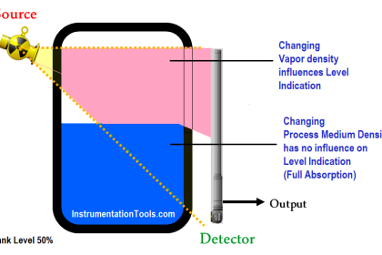
High pressures/temperatures reduce the propagation velocity of the measuring signals in the gas/vapour above the liquid interface to be measured. The result of the high pressure/temperature is a systematic measuring error.
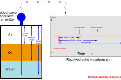
Guided Wave Radar Level Sensor
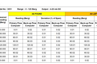
Table gives several measuring errors for different gases/vapours.
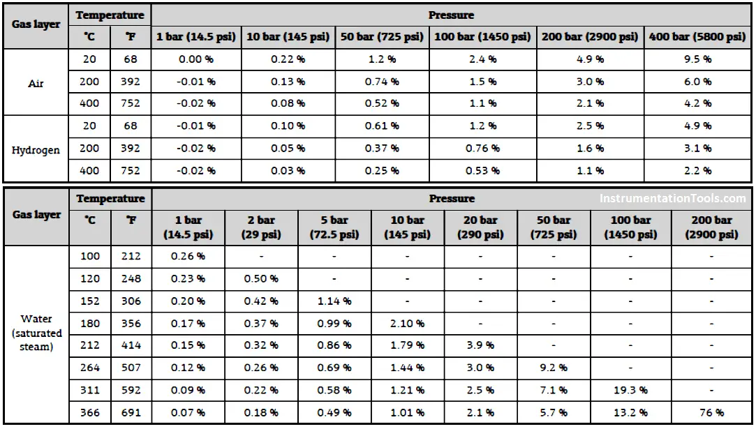
Table – Example of measuring error on wave radar with high pressure/temperature
These errors may be compensated with two main methods:
- compensation with external pressure and temperature sensors
- compensation with a reference signal.
Compensation with external pressure and temperature sensor is achieved by calculation with external pressure and temperature sensors.
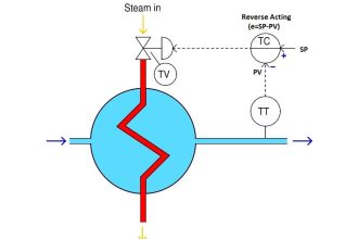
Compensation with a reference signal means that the actual wave velocity is measured by calculating a reference reflection between two known points a known distance (Lref) and relevant transit time.
Lref = Actual Velocity × Transit time of this Lref.
Having this Actual Velocity in the media, the distance can be calculated from the actual reflection time measurement. The Lref should be upper the higher maximum interface level with a margin (e.g. 150 mm in Figure).
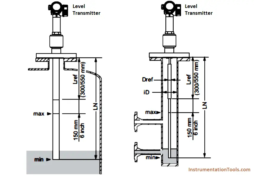
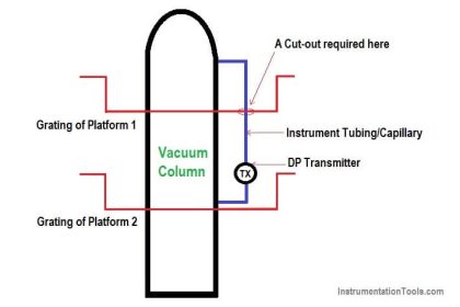
Figure – Example of high pressure/temperature compensation with reference signal mounting arrangement
Source: International Association of Oil & Gas Producers
Acknowledgements: IOGP Instrumentation and Automaton Standards Subcommittee (IASSC), BG Group, BP, Endress + Hauser, Emerson, Honeywell, Krohne, Petrobras, PETRONAS Carigali Sdn Bhd, Repsol, Siemens, Statoil, Total, Vega, Yokogawa.