Today in this article we will discuss about the root cause analysis of an incident in which one unit of a plant tripped due to work on an incorrect tag.
The incident we are going to discuss can occur in any plant if a technician or working personnel does not pay proper attention to the job.
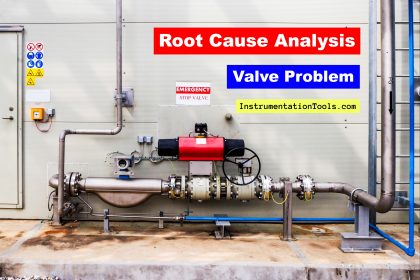
Plant Trip Due to Work on Incorrect Tag
One of the units in the crude plant of a refinery had an issue with a pressure transmitter. The pressure transmitter was single-line equipment and was having issues with fluctuations.
So, maintenance activity for the pressure transmitter was planned. On the low-low pressure alarm of the pressure transmitter, a pump was having an interlock.
The pump will trip on the low-low pressure alarm. A total of three pumps were installed in the same area for the same purpose.
All the transmitters of these 3 pumps were installed in a single skid together. During the activity on the pressure transmitter of pump A, pump B tripped.
So, what can be the reason for the tripping of pump B?
The technician verified the pressure transmitter on which the job was to be done. The tag number of the pressure transmitter (PT-A) matched with the tag number mentioned on the permit (PT-A).
As soon as the technician isolated the pressure transmitter from the manifold, the pressure of pump B went to 0.5 kg/cm2 on the graphics.
At the same time, pump B tripped. Hence, work on the incorrect tag was clear.
But when the Engineers went to see the pressure transmitter, the tag on which the technician was working was correct.
So further checking was planned. The impulse tube of the pressure transmitter was traced. On tracing the impulse tube, it was observed that the pressure transmitter was connected to pump B.
Also, the pressure transmitter of pump A was traced. It was observed that the pressure transmitter connected to pump A was different. The tag number of the pressure transmitter connected to pump A was PT-B.
Definitely, the tripping of pump B was due to incorrect tagging.
The tag painting was incorrect due to which the tripping of pump B occurred.
So how can we avoid such problems?
- Usually, the cables of every transmitter have an aluminum tagging. In this case, the aluminum tag plate was missing.
- Also, the display of some transmitters can be configured to show the tag number also. In this case, the tag number on display was left blank.
- One more thing to avoid such problems is that when we go for doing the job on any transmitter, always confirm the value with the panel engineer. The value in the field should match with the value on the graphics. This step will eliminate the work on the incorrect tag.
- Here for all 3 pumps, a common skid for mounting transmitters was given. So, during the commissioning phase, try to separate a group of transmitters for dedicated equipment.
If you liked this article, then please subscribe to our YouTube Channel for Electrical, Electronics, Instrumentation, PLC, and SCADA video tutorials.
You can also follow us on Facebook and Twitter to receive daily updates.
Read Next:
- Vibration Probe Analysis
- The compressor Did Not Trip
- Root Cause Analysis of Valve
- Heat Exchanger Tubes Corroded
- Pump Trip Root Cause Analysis


Good Day,
i am following the issued technical topics which have very good issues i am now little bit busy but in coming future i will try to write some good
thinks a lot for your great effort