Root Cause Analysis (RCA): 8000 RPM, 8000 kW, Turbine Problem Threatened Yearlong Total Fertilizer Complex Outage.
| Article Type: | Root Cause Analysis (RCA) |
| Category: | Mechanical |
| Equipment Type: | High Speed, Hi KW Major Rotating Machines |
| Author: | S. Raghava Chari |
Note: This root cause analysis (RCA) is from real-time scenarios that happened in industries during the tenure of one or two decades ago. These articles will help you to improve your troubleshooting skills and knowledge.
Introduction
By late 1960s energy efficient large up to 1500 T/d lower pressure (250‑bars) ammonia (NH3) convertors had proved themselves. Max 120 T/day 450‑bars pressures NH3 convertors only were available till then.
Side by side, high speed 10000-16000 RPM centrifugal compressors technology progressed to feed enormous high pressure gas and air volumes for the complex technology high capacity plants and their same RPM drive turbines technology to use the plant waste heat generated large steam quantities.
Many in India hesitated putting such huge capacity ammonia plants wrongly fearing India is immature to handle such complex technology, machines, and plants.
Yet a South Indian fertilizer plant realizing the day’s crying need pioneered the new technology a 750 T/d NH3, 1000 t/d urea, and 2×500 T/d NPK fertilizers plants at Chennai India.
Its success ushered many more still higher capacity new technology fertilizer plants in India’s natural gas belt; thanks to that and other measures, the 350 million population country that survived by implementing 180 grams grains/day/head rationing in the fifties not only feeds enough to its four times present population but also exports food to several countries.
Turbine Problem
An alert field operator timely field PB press tripped the 8000 kW, 8000 RPM process air compressor K-602 drive turbine K‑602 T, seeing smoke from a bearing.
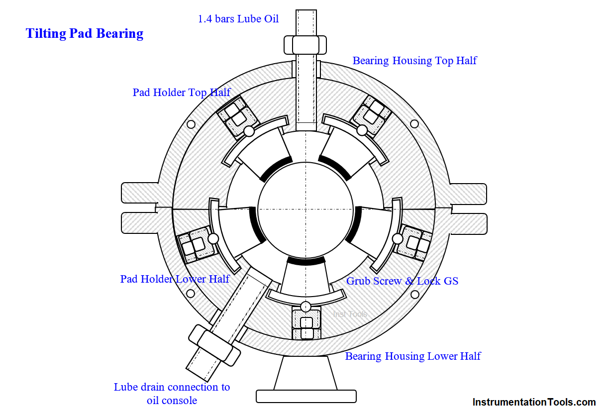
The complex ground to a halt. The crew dissembling the smoke emitting drive end Tilting Pad Bearing (TPB, fig‑1 – see boxed information on TPB) found all its pads’ Babbitt wiped out and the Rotor Journal (RJ) heavily scored.
The crew found lube filter element paper chip blocking the lube feed orifice caused this catastrophe. The fortunate timely tripping prevented the turbine wreck.
The plant on the author’s suggestion named the rotor inside the factory assembled machine Rotor-A (e.g. K-602 HP Rotor‑A, K‑602 T Rotor-A etc.) and the later purchased spare rotors K-602 HP Rotor‑B, K-602 T Rotor-B etc).
This resolved the hopeless 5-years long confusion in telling these apart using names of “Running Rotor” and “Spare Rotor”, or referring these by using the arm length and mind-boggling vendor serial numbers.
Unfortunately, K-602 T Rotor-B was in the US vendor shops for refurbishing improvements.
In-house or even countrywide repair facilities and experience to repair the high RPM machines absence required sending the failed rotor‑A also to the US turbine manufacturer.
Hence, the yearlong total complex outage threat, despite overtime authorizing for rotor B repairs!
The US citizen Managing Director (MD) – formerly American Oil Co refinery rotating machine engineer – assembled all engineering disciplines chiefs and asked them to offer a quick solution.
While high-sounding jargons e.g. fine balance, high-speed balance, at speed balance and critical speeds etc. intimidated all else were silent, the author (instrument engineer then) based on his experience during engineering college training in a diesel engine workshop 15‑years back, suggested under-sizing the journal, rebabbitt the wiped pads’ and machine them to suit the undersized journal dia.
He added, we have no grinders in our shop; but can get by using a tool-post grinder fitted to a lathe. All laughed derisively as if an untimely joke! But the MD’s stern look silenced them.
He said, “What Raghav says is no joke; try it deligently; we have nothing more to lose; but if it works we would be on top of the world.” He asked the maintenance manager to associate the author in the turbine restore all efforts.
The author pep talked the equally intimidated and hence hesitant workshop engineer, “First, call the Babbitt lining shop owner to rush here. The injured rotor will be here in couple of hours; cheerfully load, center and grind off the journal blemishes successfully and you will be the day’s hero!”
He continued, before the rotor reaches the shop, fit the finest grit grinding wheel fitted tool post grinder to the most accurate lathe and try it out on a test piece. In addition, ready the super finishing attachment to super finish the journal to 0.4 μm RMS.”
The plant had bought the German attachment, super finishing stones and cutting oil to super finish plunger pumps plungers for long leak free service.” Boxed is the information on super finishing and how to check it.
Tilting Pad Bearings
Tilting Pad Bearings (TPB) support the journal on babbit lined segmental shoes or pads – commonly five P1-P5; distributed around the journal 720 apart (Fig 1); each pad covers »15% of the journal periphery.
Pad Holder Bottom PHB holds P1 to P‑3 in their locations while PHT P4 & P5. 1.4-bars lube oil flow through the TPB and rotor rotation swivel each pad to the most suitable position to form the best journal supporting oil film to offer exceptional rotor stability.
The common split journal bearings supported rotor shafts are prone to ≈½xRPM frequency excessive oil-whips caused vibrations at > 5000 RPMs; but, not TPBs supported shafts.
In addition debris if any drain harmlessly with the oil via the inter-pad gaps, averting potential scored journals and pads, commonly seen in failed JB by trapped dirt in the annulus.
5‑micron dual filter system filtered Lube oil controlled at 1.4 bars evenly flows into each of TPB via itsrestriction orifice for lubrication and cooling.
Audio visual alarm warns the operators at lube pressure < 0.8 bar and safety systems trip the machine at<0.6 bar to prevent failed lube machine wrecks.
The rotor reaches the shop
Without awaiting instructions, field crew had disassembled the turbine, brought it to the shop and helped the shop machinist to load and center the Rotor A on the most accurate lathe chuck.
Elapsed times (ET) from plant stop 0+8 hours
Journal blemish grinding at shop
During turbine disassembly, a machinist fitted a tool post grinder on the lathe and tried on a test piece.
The author encouraged machinist started grinding the journal in small steps till blemishes disappeared. Elapsed time (ET) 0+8+4 = 12; hours; Journal finished dia 99.8 mm – original 101.6 mm (4”)
Journal super finishing
As soon as blemish grinding was over, the machinist removed the tool post grinder, fitted the super finishing attachment on the lathe, and super-finished the journal 0.4 microns RMS. ET- 0+12+3 = 15
Pads Re-babitting
The rush telephone called re-babitting vendor collected the pads at ET 0+2.
The author’s second pep talk, (the days 2nd), the high speed machine jargons intimidated rebabbitt shop owner hesitantly agreed to rebabbit the pads on ‘no guarantee best effort basis’ only.
Pads Machining
The author, the shop foreman and an ace machinist huddled in a table immediately after journal grinding started to find out a way to machine the 5 Nos. 60O cylindrical segment shaped pads (fig 1).
Few minutes later, the author proposed using the very holder to hold the pads for machining; seeing the group’s puzzled looks, he continued, normally we position a pad in the holder slot, tighten the grub screw hand tight and unscrew it ¼ turn to enable the pad swiveling and tighten the lock GS; now just hard tighten the GS and lock GS. The group thought for few minutes and ½ heartedly said it might work.
The author said, “don’t OK it ½ heartedly; let us try it and be sure of it.” Madhav, the machinist borrowed a spare pad from the warehouse, and fitted as told. The group’s strong man gripping the pad with a pump plier and max force twisting did not nudge the pad.
Though satisfied of much stronger than necessary securing for machining the soft babbitt, Madhav asked, “The pads are 72o apart; i.e., I have no place to measure the pad bore; how to measure the pad ID while machining and at stop at final dia?”
The author said, “It is easy Madhav, “just borrow a 95 mm outer dia antifriction bearing from the warehouse butt it against pads 3 and 4 IDs and check the gap between the pad 1 bore and the AFB bottom with feeler gauges.
I guess, this is lot easier and lot more accurate than with a micrometer; ET 0+3.
Rebabbitted Pads Reach
The relining vendor delivered the rebabbitted pads; ET 0+10
Pads Machining
A machinist clamped the rebabbed pads to the pad holder as explained above and centered it on a lathe. He borrowed the 95 mm AFB and feeler gauges and kept near the lathe; ET 0+11.
At ET + 12 he knew the journal finished dia is 99.8 mm. He started machining the pad bore; checking with the 95 mm AFB and feeler gauges he finished the pad bore ID to 99.8 +0.130 against the max specified 99.8 + 0.150 mm the max clearance. Pads were ready for use at ET + 13.5.
Turbine Assembly and Slow Roll
Turbine assembly started at ET 0+15. The crew handed over the turbine for slow role at ET 0+21. Assembly time was 2-hrs less, as bolting back the high temp grease well lubed bolts was a piece of cake unlike unbolting the rust and heat frozen bolts dissemble.
The maintenance manager constantly monitoring the turbine restart jobs progress informed the Managing Director the turbine slow roll 2 hours before. Both reached the plant with a pundit and puja samagri ET 0+20. The pundit readied for Puja.
As soon as the millwrights signaled, the Pundit completed the Puja in ½ hour and distributed Prasad. The turbine slow-rolled at ET 0+21½ hours – a remarkable and nowhere else attempted achievement indeed.
Super-finish & its verification
Elaborate instruments using complex electronics telling exact RMS values of super-finish are available with large-scale manufacturing shops like auto parts makers, Indian Institute of Technology etc. Fortunately, super-finish qualitative checks using inexpensive calibrated plastic or metallic feeler gauges are adequate for most purposes.
A 270x100x15 mm box containing several labeled commonly used surface finishes feeler gauges is available. One just runs One’s fingernail on the calibrated feeler of desired value; register the feel in his mind, and the same person runs his fingernail on the super-finished job immediately.
The same feeling confirms super-finish correctness. This very reliable and repeatable qualitative check is adequate for most tasks like super-finish checking rotors’ journals, pumps’ plungers, valve stem packing area, compressor piston rods at seal locations etc. and numerous other sliding surfaces applications.
Stop Recurrence
During repairs progress, another crew wrapped fine SS gauze over all the machines’ paper filter elements to prevent such failure recurrence.
In addition, the plant replaced the dual filter system paper filter elements with metallic elements received six months hence, online.
The MD congratulated the repair team on everyone in the field.
The shop repaired rotor was still in service when the author left the plant 10‑years later for another assignment.
Author: S. Raghava Chari
Do you face any similar issues? Share with us through the below comments section.
If you liked this article, then please subscribe to our YouTube Channel for Instrumentation, Electrical, PLC, and SCADA video tutorials.
You can also follow us on Facebook and Twitter to receive daily updates.
Read Next:
- Process Air Compressor Overhauls
- Heat Exchanger Root Cause Analysis
- Mechanical Variable Speed Drives RCA
- Compressor Case Discharge Temperature
- TEFC Motors Rampant Winding Burnouts