Instrumentation engineering root cause analysis (RCA) of butterfly control valve failure caused serious vicinity heavy fire in a plant.
| Article Type: | Root Cause Analysis (RCA) |
| Category: | Instrumentation |
| Equipment Type: | Control Valves |
| Author: | S. Raghava Chari |
Note: This root cause analysis (RCA) is from real-time scenarios that happened in industries during the tenure of two or three decades ago. These articles will help you to improve your troubleshooting skills and knowledge.
Butterfly Valve Failure Problem
Problem: A fertilizer plant’s fire and volunteer crews’ hourlong hard and heroic efforts put out ammonia converter vicinity seen a huge sudden fire.
Observations
The operations crew reported TCV 701 shaft non-drive end missing; the resulting enormous volumes 400o C, 220 bars syn gas (75% H2+25% N2) spill auto ignited into the huge fireball.
Dissembled Valve Observations
TCV 701– 10” 2500 # wafer body Butterfly valve shop-dissemble inspection findings are:
- The broken 10 mm diameter shaft non-drive end (NDE) missing; found later 50 m away on the floor
- Obviously, the 220 bars, 400O C syn gas enormous spill gush out auto ignited into the very hard to put out fire. Pressure could not eject the shaft drive end attached to the actuator.
- The disc hub bore to the SS 316 shaft clearance was around 3-mm i.e., too loose fit up
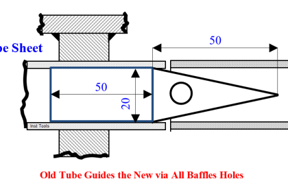
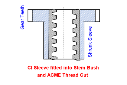
- A 12 O’ Clock position pin and a 25 mm away 3 O’ Clock position pin (fig) lock the disc to the shaft. This one end only lock allows the chrome-moly disc and different thermal expansion coefficient SS 316 shaft expand stress free: hence essential.
Why the Shaft Broke Root Cause Analysis
Flow turbulence flutters the one end only secured disc in the too high hub gap, enlarges the pin holes, gradually the shaft cross section at pin hole decreases and after 7 years’ service the too weak at the pin hole shaft breaks Line pressure ejects out the broken shaft NDE like a bullet. No injuries or fatalities from this were sheer luck!
The Author Recurrence Prevention Solution follows:
- The immediately ordered 10% stronger K‑Monel shaft for abundant safety would take 6 months to reach; hence, the shop shall make:
- 10 mm d7 tolerance SS-316 shaft gland areas super finished, and a diameter line center punch-marked at an end
- Weld fill the disc hub locking pinholes and file it flush
- Increase the 25 mm OD Disc Hub bore diameter to 16 mm H7; this leaves enough wall thickness at the hub.
- Make a 16 mm d7 diameter x length = disc diameter SS 316 piece
- Slide fit the piece into the hub bore file off excess piece portions disc diameter flush
- Bore the piece ID 10 mm H7 to accept the shaft at near-zero play
- Loosen the valve body DE and NDE glands 3-turns
- The author wanted taper pins driven in the same taper holes to snugly lock the shaft to the disc hub, akin to a drill chuck tightly gripping taper shank drill.
- How to drill the so small diameter taper hole baffled the author! He thanked and appreciated the machinist, for his timely solution: Center a 2-4 mm diameter taper reamer on a lathe chuck. Hold the cutting tool on the tool post. Adjust the tool travel angle by trial and error to trace the taper reamer’s taper.
- Make two 30 mm long 3 mm large diameter taper pins by moving the tool post fitted tool. Thus, the lathe turns out taper pins of the same taper as the taper reamer
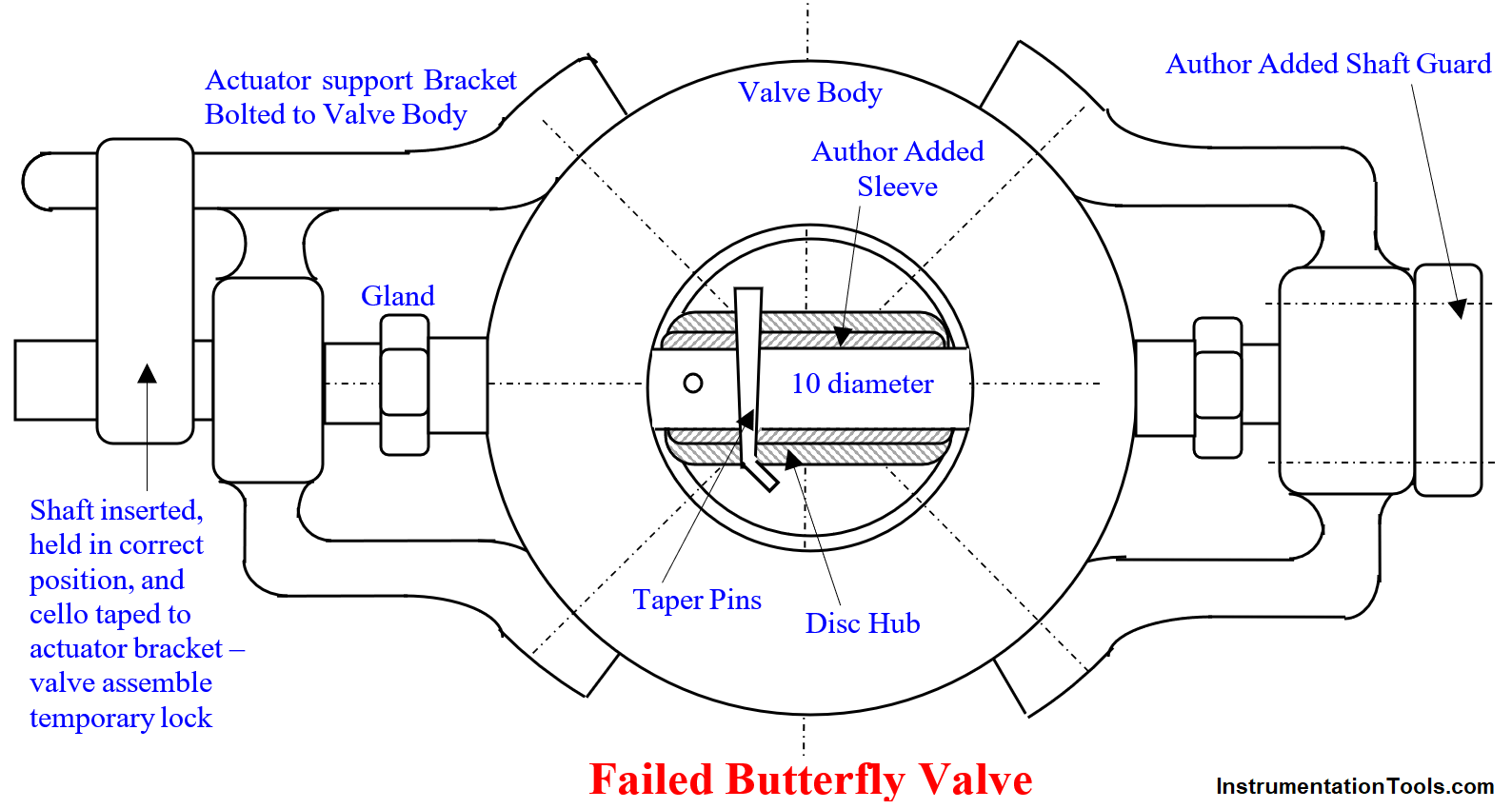
- Assemble the disc shaft and body into a butterfly valve (fig 1)
- Center and lock the disc to the valve body bore in valve closed position driving wooden taper wedges 120o apart
- Turn the shaft till the diameter line shows a closed valve and cello tape lock it (fig 1)
- Drill a 2.5 mm diameter vertical all the way hole on the disc hub 10 mm away from disc left end. Run the taper reamer in the drilled hole till it projects 10 to 15 mm at the other end. Insert one of the taper pins, hammer it in hard and bend the small end slightly avoid it coming out.
- Similarly, lock the disc to the shaft driving a taper pin in a taper hole at 90O to the first 25 mm away – see fig.
- Bolt the shop made shaft-guard (fig 1) – author added part – to prevent ejection and fire – if ever the shaft breaks despite the added failure prevention features – a redundant safety step.
- Tighten the step 3 loosened DE and NDE gland nuts 3-turns to avoid gland leaks. Remove the shaft temporary cello tape lock
- Assemble the actuator to the body and calibrate the valve positioner
A millwright and instrument technician team bolted the CV to the pipeline, connected the signal, and air supply tubes, and established the air supply
RCA based repair Benefits
Thus, repaired valve never failed. The manufacturer thanked the informative feedback, appreciated, and includes the improvements, with thanks in their then-on products.
Author: S. Raghava Chari
Do you face any similar issues? Share with us through the below comments section.
If you liked this article, then please subscribe to our YouTube Channel for Instrumentation, Electrical, PLC, and SCADA video tutorials.
You can also follow us on Facebook and Twitter to receive daily updates.
Read Next:
- Passing Control Valves
- Errors and Faults in Siemens PLC
- Repeat Failures of Letdown Valves
- Pressure Taps Block Valves Leaks
- Drifting Values of Transmitter