The purpose of the machine condition monitoring system shall be desired to accept a variety of transducer inputs and continuously monitor and display appropriate machinery parameters alarms are generated.
When the conditions exceed user established limits. These alarms are used to automatically shutdown the machine or to annunciate machinery problems to operators and other plant personals.
In such a machinery monitor conditioning system one of the essential parameters is vibration.
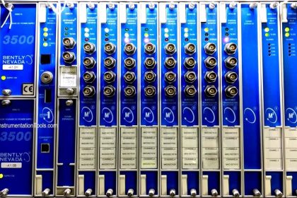
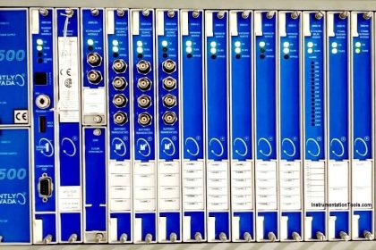
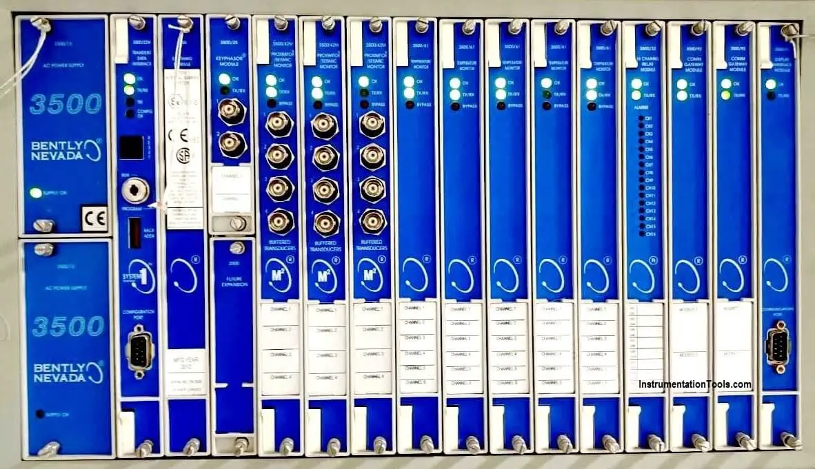
In general, we use the Bently Nevada 3500 machine monitoring system.
To find out vibration, following things are required
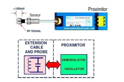
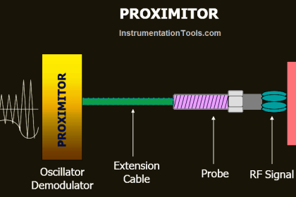
- Vibration probe
- Proximity
- Extension cable
- Multimeter
Vibration measurement units are mills.
Micrometer
It is on the SI unit of length equal to one million of a meter, or equivalently one thousand of a millimeter.
It is also commonly known as a micron. It can be written in scientific notation as 1*10-6 m , measuring 1/10,00,000 mill-unit of length or displacement equal to 0.001 inches or 25.4 micrometers.
Probe
Specially a proximity probe transducer sometimes used to describe any transducers.
Probe Gap
The physical distance between the face of a proximity probe to tip and the observed surface the distance can be expressed in terms of displacement (mills, micrometer) or in terms of voltage (millivolts) standard polarities convention dictates that a decreasing gap result is increasingly less negative output signals.
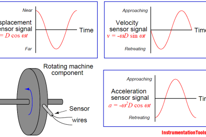
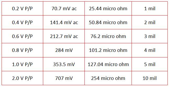
Proportional Values
Direct vibration amplitude, probe gap, and other vibration amplitude and phase information proportional values are mentioned below.
Vibration Probe Field Settings
- Measure the vibration proximitor drive voltage between common an V/T. It should be -24 VDC
- Measure the DC output voltage between common and output. It should be between -9.5 V and -10 VDC (as per company this voltage standard will variable) if the output voltage is not between -9.5 V and -10 VDC then the vibration probe will need to be set.
- Remove the vibration probe cover and slacker off the probe lock nut with two spanners. One on the lock nut and other on the probe adjustment nut adjust the probe depth until the reading on the voltmeter is between -9.5 and -10 Volts.
Note: If the reading is below -9.5 V then the probe must be slacked (anticlockwise). If the voltage is above -10 V then probe must be tightened (clockwise). When the correct voltage is obtained tightened the bollon lock nut. Refit vibration probe cover.
- If the probe adjustment does not affect the voltage reading try & different probe and if this does not work replace to vibration interface proximiter.
- If the fault is still present, move the CO-AX cable from both the proximiter and the vibration probe-measure resistance of the CO-AX cable by placing a short circuit between the cable center conductor and the shield at line another end.
- The resistance should be approximately 0.8 ohms per meter length
If a reading of zero or over 10 ohms is obtained then the cable is faulty and should be replaced.
Read Next: