Root Cause Analysis (RCA): 10-m Elevation Tubes Corroded 20 T Weight Heat Exchanger E-201 A removed; Positioned New E 201 A; re-tubed old E 201 A for use as E‑201 B.
| Article Type: | Root Cause Analysis (RCA) |
| Category: | Mechanical |
| Equipment Type: | Heat Exchanger |
| Author: | S. Raghava Chari |
Note: This root cause analysis (RCA) is from real-time scenarios that happened in industries during the tenure of two or three decades ago. These articles will help you to improve your troubleshooting skills and knowledge.
Heat Exchanger Tubes Corroded
Recycled liquid ammonia contained small % carbomate content corroded carbon steel tubes caused so many shutdowns vexed urea plant ordered SS 316 tubes fitted NH3 condenser E‑201 A, decided to install it during a turnaround (TA), re-tube the removed E-201A with SS tubes and install it during the following TA in place of E-201B.
The maintenance manager asked the author, the instrument engineer then to get the new E201s installed as he was relatively free while the Mechanical and Electrical Engineers were still firefighting the never ending Mechanical and Electrical Problems. He promised assigning a very good crew leader.
The author accepted it. He called the to be used 100-T rented crane driver and rigger, showed them the heat exchangers located at 15 m elevation and asked them where they would park the crane to lower the exchanger to the ground and march it to the place where he will re-tube it.
As the compressor house adjoined the heat exchangers’ east and various pumps the west and other equipment south the only open space was to the heat-exchanger (HE) north.
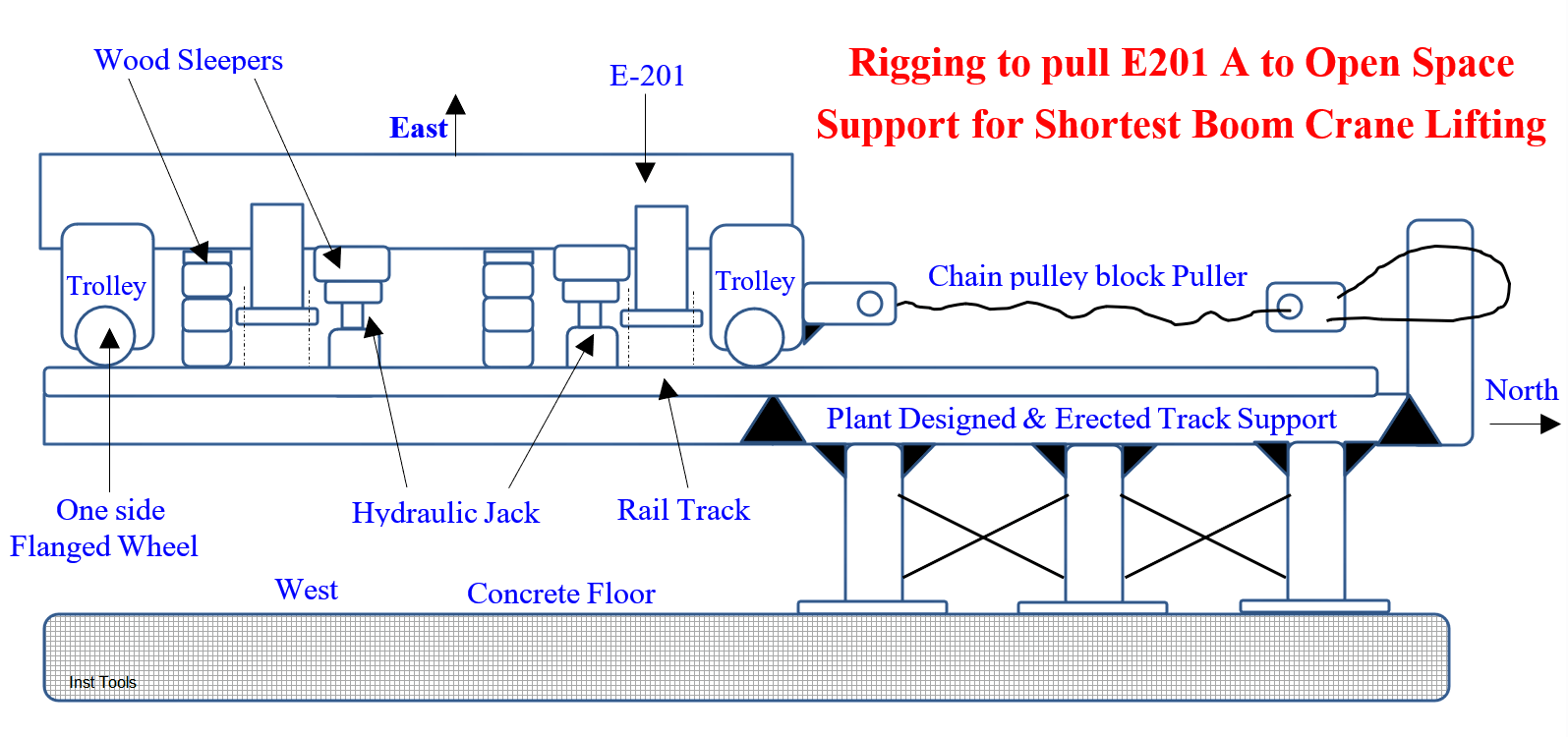
Hence, the crane driver and rigger asked the author to build a rail track support (RTS) heat exchangers north about 1.5 mm longer than the heat exchanger. They will build the track on the RTS within two days of TA.
The plant must give the necessary hot & cold work permits. They will park the crane RTS east or west, lift the heat exchanger with the boom near vertical, march and position it at the re-tubing place. After that they will position the new E-201A on the old E-201A left vacant spot.
RTS Making
The author gave 250-500 mm I beam, channels and >16” pipes’ store held quantities list to the design engineer (DE), took him and his drafter to the heat exchanger (HE) and explained the needed RTS and its purpose.
The DE designed a RTS consisting of pipe pillars supported I beams to lay the rails. The plant workshop made it when it had no other urgent plant work in a month.
A petty contractor using the plant’s crane positioned the RTS suitably to receive the E201A and welded to the grill support I‑beam.
Pulling the to take out E-201A on the rails to the Open Area during the turnaround (TA)
The plant crew after getting work permit unbolted the exchanger base bolts and connected piping for lifting it.
The crane, two trolleys, rails hydraulic jacks etc. loaded on a low bed trailer, entered the plant the day after TA start 8 AM, as the author scheduled.
The plant’s crew leader escorted them to the E‑201A vicinity and called the author. The author strictly stopped the crane driver who insisted on marching the crane to the ground from its 0.8 m above bed.
An obliging bagging plant engineer filled sand in 100 Nos. old bags, hauled them to the E‑201 site and spread the bags for the crane to march down as the author requested.
Thanks to this arrangement the 100 T long boom crane on which the entire E201 job depended descended to the ground safely and undamaged.
Cutting short further details, which won’t interest the general readers, the crane crew laid the track, positioned a trolley at E201 head end the other at tail end, positioned E201A on the trolleys using hydraulic jacks and wooden sleeper supports and dragged the trolleys to the open area.
Suitably placing the crane and boom nearly vertical the crane crew lifted and lowered the 20 T weight E201A, marched and positioned it at the re-tubing spot.
Likewise, the crane crew positioned the new E201A on its foundation and the plant crew bolted it. Plant piping crew connected the vapor NH3, liquid NH3, Cooling Water in and out lines and handed over for operation.
They cleared the area of all construction items and returned the borrowed items to the tool crib.
Removed E‑201A re-tubing
A week after the TA the author started re-tubing removed E201A with SS 316 tubes: as the crew leader assured his heat exchanger re-tubing competency.
The author asked him to remove one tube only and insert the new SS tube in its place, just to find out re-tubing problems if any. He walked away to check on other jobs.
3-hours later the crew leader requested the author to reach the re-tubing site. He sheepishly grinning said, “Sir, thanks for telling us to remove one tube only and put the new tube in its place.
We removed one old tube alright; but the inserted new tube hits the baffle, maybe due to sag; we are stuck up help us out sir.”
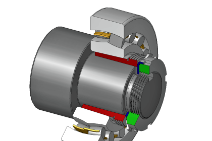
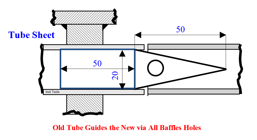
The author anticipating this situation had thought of a way out: he showed the 6 Nos. shop made mandrels (fig 3). Touch a 20 dia x 150 long bar on the old tube, hammer the bar and drive out the old tube 10 mm away from the other tube sheet.
Insert a mandrel cylindrical end in the new tube end. On pushing the mandrel fitted new tube inside the tube sheet hole; the mandrel cone penetrates into the new tube.
The gradually pushed new tube easily passes through all the baffles’ holes, as the mandrel and old tube combination guides it. This way you can insert all the new tubes into the exchanger.
Remove the mandrel out of the new tube by inserting a rod in its hole and pulling it out. As for the first hole, where you have removed the old tube, just weld a plug each to the tube sheets holes.
The heat-exchanger (HE) with one less tube is also fine. Another advantage of letting the old tube guide the new tube is new tube insertion itself removes the old tube; i.e., cuts ½ the re-tubing time!
The leisurely done re-tubing was over in 10-days working normal hours only.
The SS re-tubed E-201A Benefits
The plant crew tagged the re-tubed exchanger E201B and installed it at a suitable shutdown opportunity.
Thanks to the SS tubes, the corrosion problems caused yearly 10-15 SDs to plug the leaky tubes and associated 15 lost on stream days and 15000 Tons/year lost Urea production vanished.
Author: S. Raghava Chari
Do you face any similar issues? Share with us through the below comments section.
If you liked this article, then please subscribe to our YouTube Channel for Instrumentation, Electrical, PLC, and SCADA video tutorials.
You can also follow us on Facebook and Twitter to receive daily updates.
Read Next:
- Process Air Compressor Overhauls
- Fan Motor Journal Bearing Failures
- Mechanical Variable Speed Drives
- Compressor Discharge Temperature
- Motors Rampant Winding Burnouts