The sensors and actuators that are connected to the inputs and outputs (IO) of a Programmable Controller or PLC are normally mounted in the plant.
Therefore the IO connections of a traditional control system often involve long runs of cable from the control room to the plant. To attempt to reduce cabling effort, multi-core cables can be used, but these require junction boxes and/or marshalling racks to route the signals to the correct location.
Consequently each IO channel can involve many connections as the signal passes from cable to cable. Such wiring is expensive to install, complex to maintain and fault-finding can be difficult.
Traditionally wired systems

Fieldbus
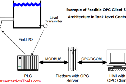
Fieldbus is an industrial network that is specifically designed for communication between PLCs or industrial controllers and the field-mounted sensors and actuators. Fieldbus is designed to replace the point-to-point wiring that connects each sensor and actuator to the controller IO.
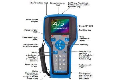
When the fieldbus is integrated into the sensor or actuator the devices often provide additional capability such as remote device configuration and/or testing over the bus.
Integrated devices can also provide diagnostic information back to the control room to help diagnose and locate device faults. Thus devices with integrated fieldbus are often more capable or “intelligent” than traditional actuators or sensors.
Remote IO stations can also be used with fieldbus wiring. Here the digital or analogue IO modules are mounted in the field, close to the sensors and actuators and the data is communicated to the remote IO module via the fieldbus cable.
However, when using remote IO the field devices cannot use the bus to communicate additional data such as parameters or diagnostics. Here, we must use traditional (non-intelligent) actuators and sensors.

Fieldbus has many advantages over conventional point-to-point wiring:
- A significant reduction in installation costs (typically 20% to 40% savings). This saving comes from reduced wiring, connections, junction boxes, marshalling cabinets, cable trays and supports etc.
- Perhaps more importantly the number of connectors and connections is drastically reduced (typically 80% reduction). This is important because most problems occur because of connector failure (i.e. open circuits, shorts, water ingress or corrosion)
- System expansion and modification is simpler and less expensive since only the additional cable run from the existing network to the new device must be installed.
- Two-way communication means that additional information such as calibration and configuration data, diagnostic and test information, device documentation such as device tag numbers; serial numbers service history etc. can be communicated over the network. Equipment maintenance and servicing become more centralized.
- Since communication is digital, accuracy is not affected by noise, interference or electrical loading effects etc. This is a particular advantage in transmitting analogue values.
- Open standards mean that multi-vendor systems can be constructed. Product certification ensures that communication will work between devices from different manufacturers.
Types of fieldbus
There are many different fieldbus types available, most of which are defined by international standards and are supported by many different manufacturers. Specific fieldbus types are often designed for particular application areas or industries.
For example, the requirements for the process industry are often quire different from those of part manufacturing or materials handling. What is suitable and cost effective for one application area is often not appropriate for another.
Sometimes we need a simple low-cost fieldbus; other times we need extensive or flexible data capability. Some fieldbus systems need to be able to operate in potentially explosive atmospheres; others require extremely high reliability for safety-critical applications. Some fieldbus systems are designed to carry power to the field devices over the bus cable (power over the bus). This is often done using just two cable cores to carry power and data.
The different types of fieldbus are generally not compatible with each other. This means that devices on a network must all use the same type of fieldbus. However, this does not mean that different fieldbusses cannot be used together in an application.
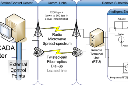
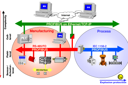
Gateways can be used to connect one type of network or fieldbus to another. These provide conversion from one technology to another and allow data to be passed between networks. Quite often an application will involve several different types of network arranged in a hierarchical manner.
Many people ask why we can’t just have one type of network for all applications and levels. The answer is that there are many different requirements for communications in separate areas of the plant and at different levels in the hierarchy.
Many different considerations must be taken into account: The required communication speed; data size and structure; environmental factors like explosion risk, wet or dirty conditions, ambient temperature variations, existence of electrical interference etc.
Some networking solutions are suitable only for clean and dry environments; others can be used in exposed locations. Cost, capability and robustness often vary greatly from one fieldbus to another.
By far the most common fieldbus is Foundation Fieldbus, Profibus, Actuator-Sensor Interface (AS-i) etc..


I consider this a price article, but apparently the issue has not been resolved.