Preparation of instrumentation documents is one of the major roles of an instrumentation design engineer. In this article, we are going to discuss various kinds of instrumentation documents used for project engineering.
Piping & Instrumentation Drawing
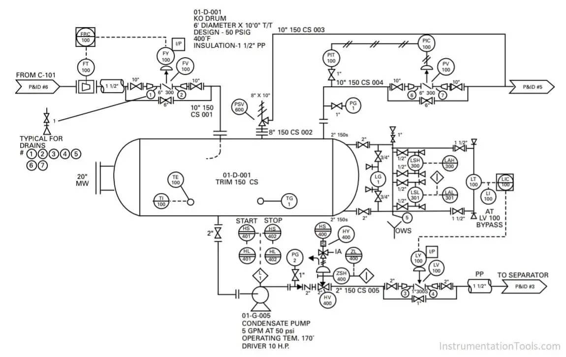
A Piping & Instrumentation Diagram or P&ID is a schematic illustration of the functional relationship of piping, instrumentation, and system equipment components.
P&ID shows all of piping including the physical sequence of branches, reducers, valves, equipment, instrumentation & control interlocks.
Audit of P&ID is to be done for proper indication of instrument symbols with respect to standard company legends or as per ISA standard.
Audit of P&ID is to be done for proper indication of instrument tag numbers as per the numbering philosophy.
Audit of P&ID is to be done for proper indication of instrument loop with interlocks.
Process Datasheet
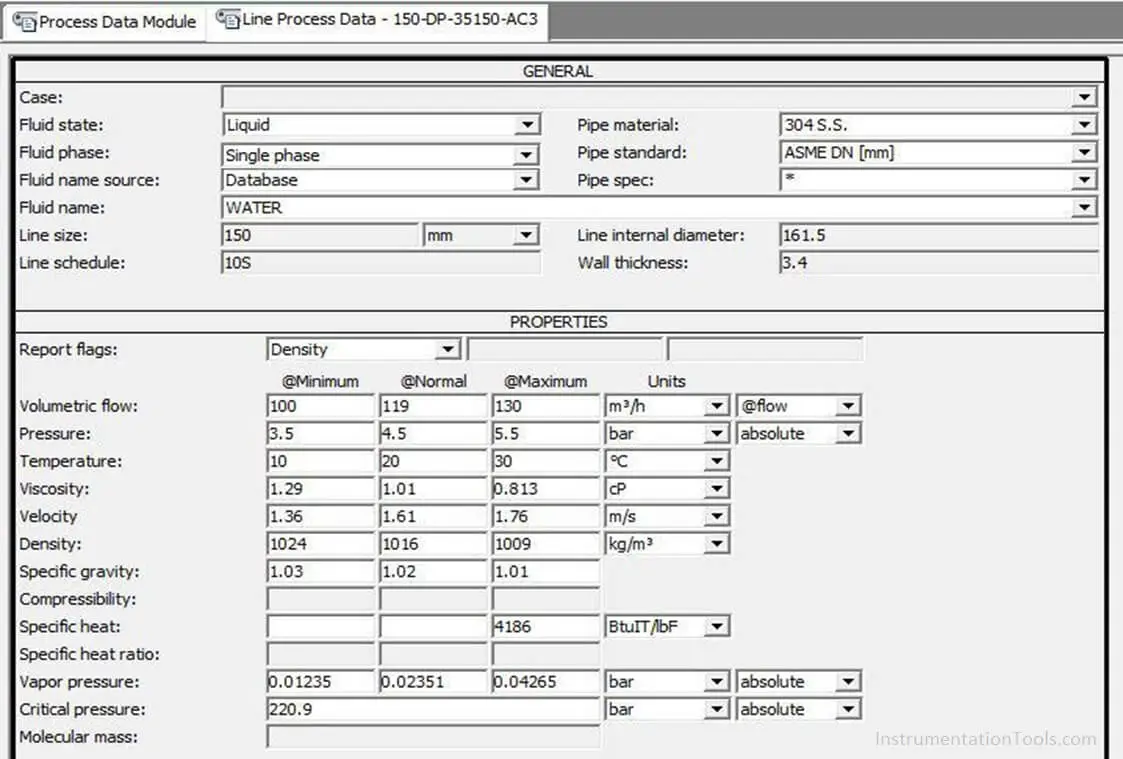
This is the most important information require by Instrument Engineer to design various instrument loops according to the services
Data needed by the Instrument Engineer shall be the properties of various components used in the process ( Liquids & Gases) and these are taken from the process datasheet.
The main data included in a process datasheet is as follows.
- Fluid Name
- Density / Viscosity
- Pressure
- Temperature
- Flow
The minimum, maximum & operating range of pressure ,temperature & flow has to be mentioned in a process datasheet.
Instrument Index
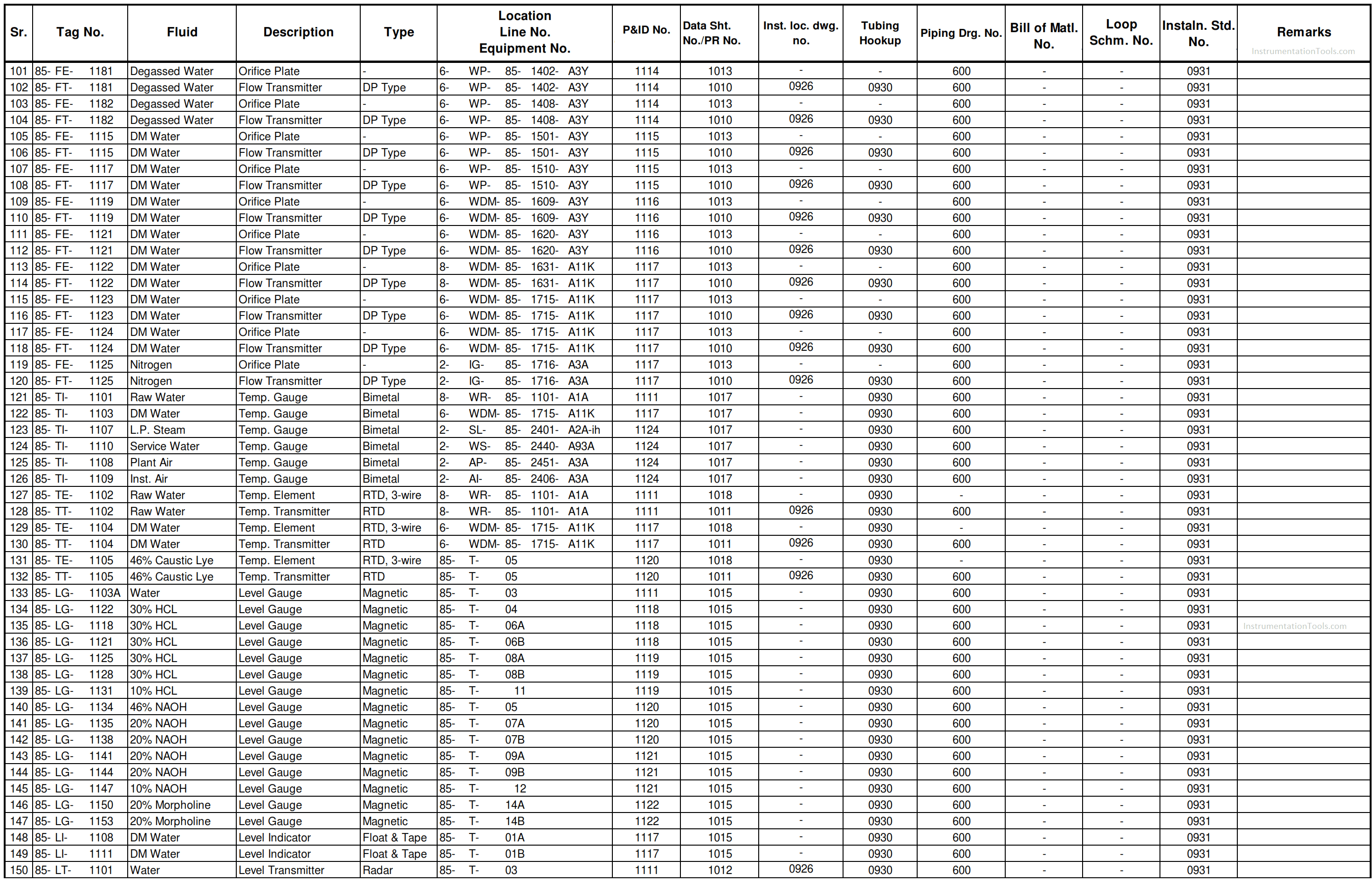
Instrument Index is made for listing all the instruments loop-wise on the basis of P&ID.
It covers all the required information of the instruments in the loop.
The major data that must include in an Instrument Index are
- Tag Number
- Description of the Instrument
- Service
- Type of Instrument
- Location of Instrument
- P&ID Number
- Instrument Specification Number
- Hook-up Diagram Number
- Instrument Layout Number
I/O List
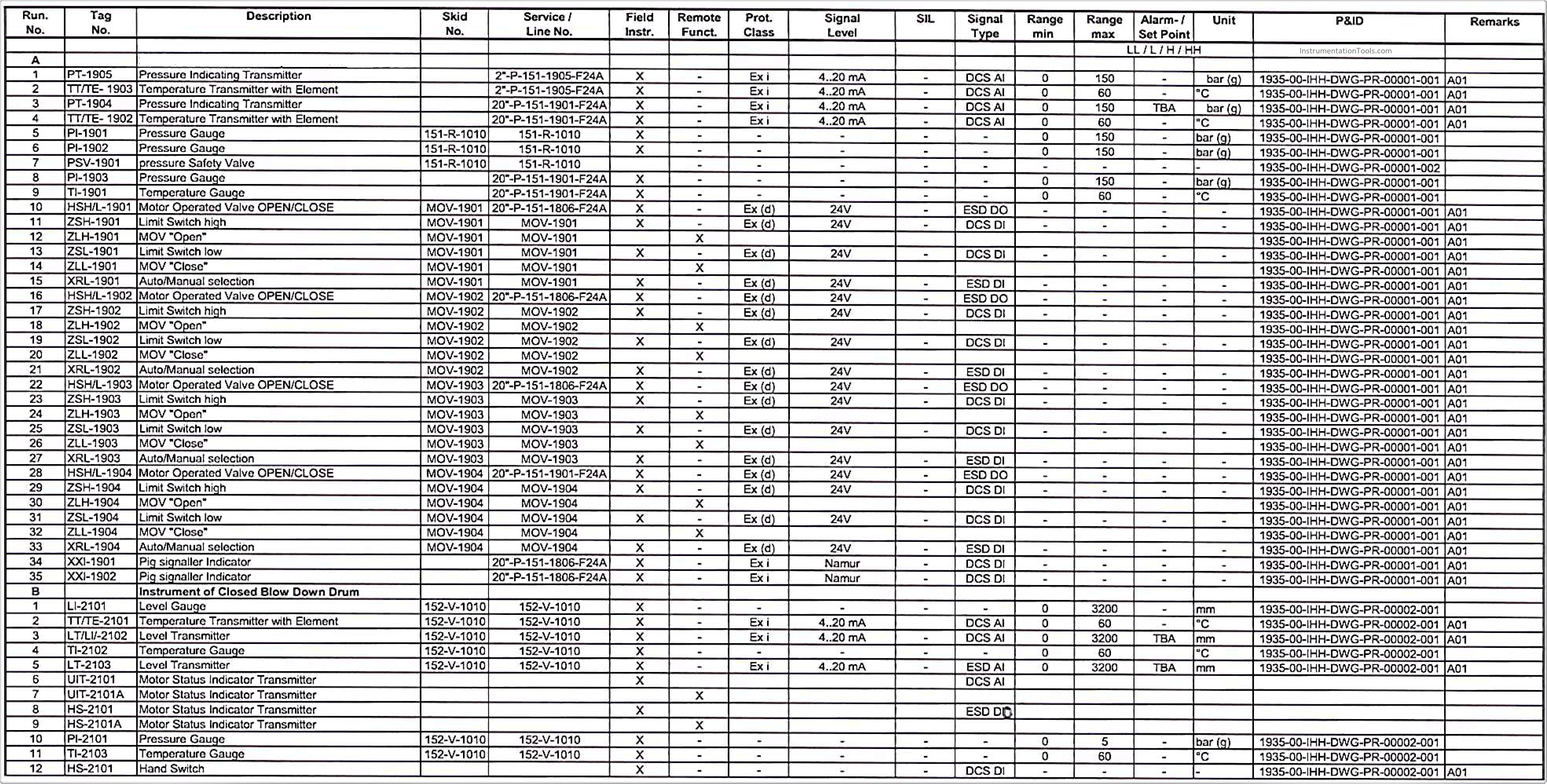
I/O List is used for defining the type of signal inputs & outputs of the instruments used.
It is mainly used for defining the number & types of signals given to PLC / DCS.
It is the basic document used for sizing PLC / DCS.
The main data that must include in an I/O List is as follows.
- Instrument Tag Number
- Service
- Signal Type
- Signal Level
- Instrument Range
- P&ID Number
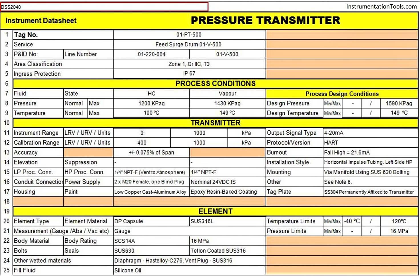
Instrument Specification
Instrument Specification documents are made with the help of both P&ID & Process Data.
It helps in specifying the precise requirement of the process for which the instrument is to be used.
Purchasing of an instrument is mainly dependent on Instrument Specification.
The major data that must include in the Specification Sheet is as follows.
- Tag Number
- Service
- Type of Instrument
- Range
- Size
- Location
- Material
- Mounting
- Protection
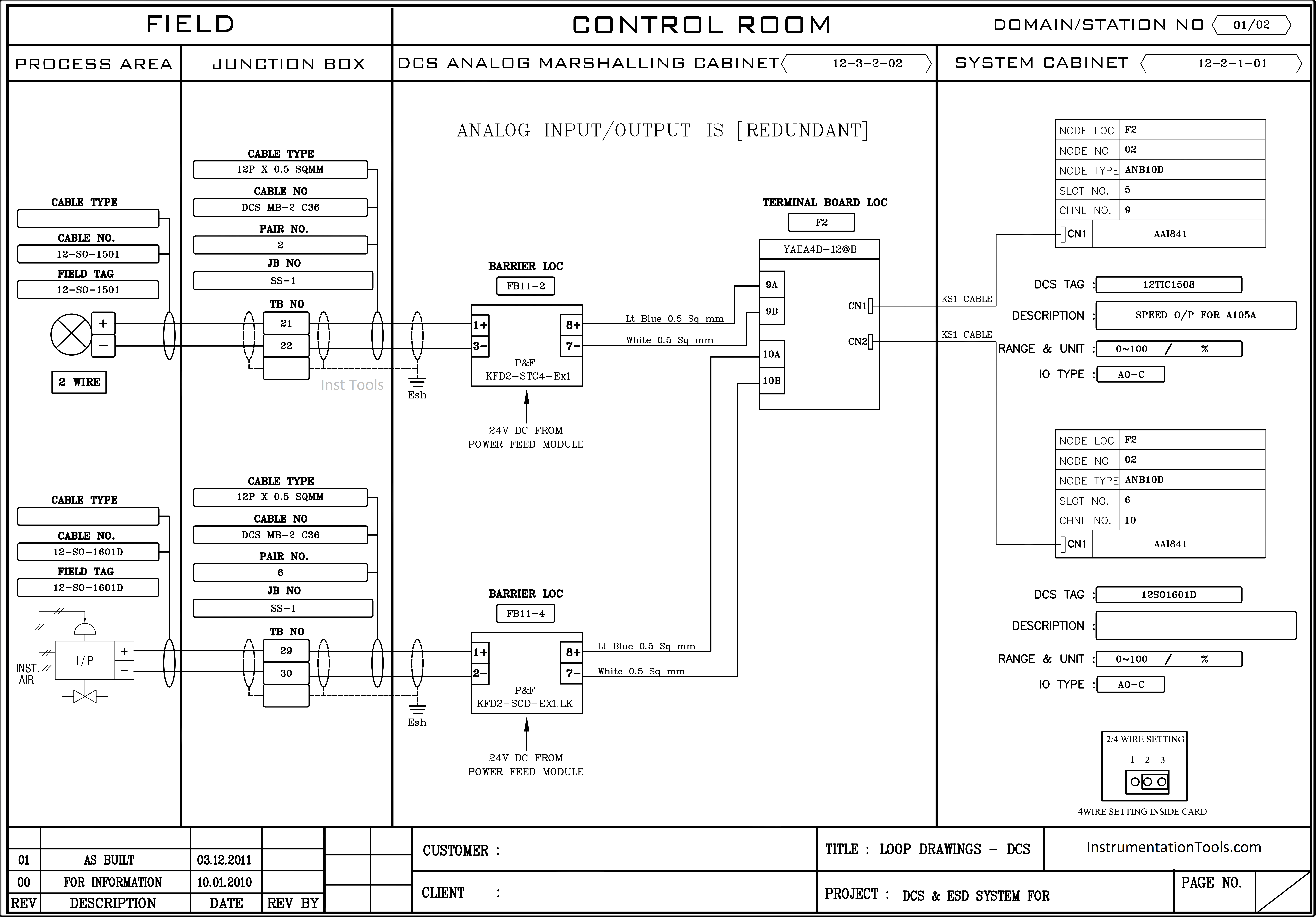
Instrument Loop Diagrams
Instrument Loop Diagrams are the graphical representation of loops.
ILDs are made using the help of P&ID, I/O List & Cable Schedule.
ILDs show the detailed flow of signal from instrument to control system cabinet.
The major data that must include in an ILD are;
- Components used the loop
- Location of the components
- Termination details
- Interlocks used
- Alarms
- Soft functions
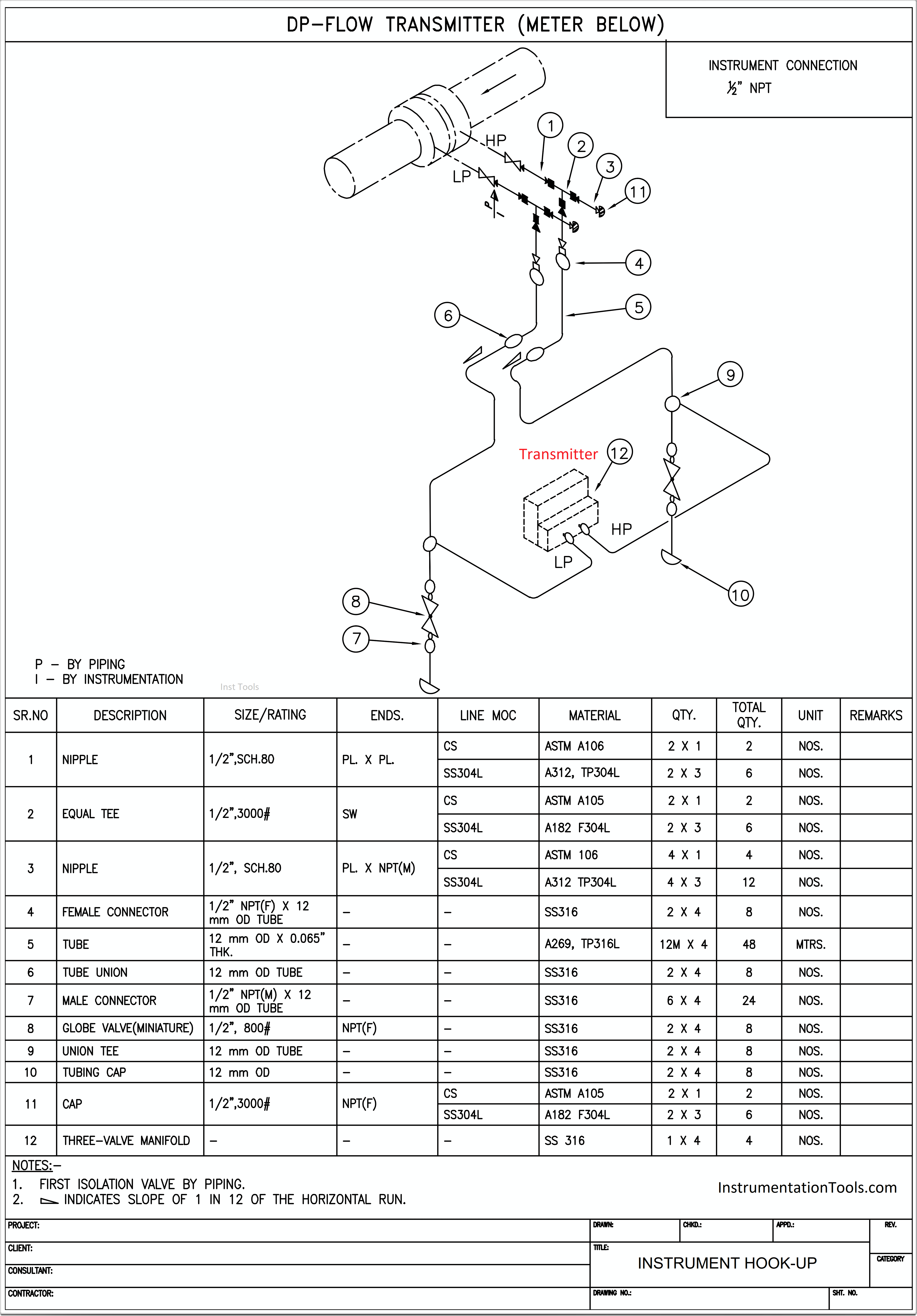
Instrument Hook-up Diagrams
Instrument Hook-up Diagrams are the graphical representation of the method of connecting instrument to the process lines, equipment, tanks, vessels, etc.
The main data that must include in a Hook-up Drawing are;
- Physical mounting of the instrument in the field
- Various items used for mounting of the instruments
- Size & material of various items used
- List of Tag Numbers for which the Hook-up is applicable
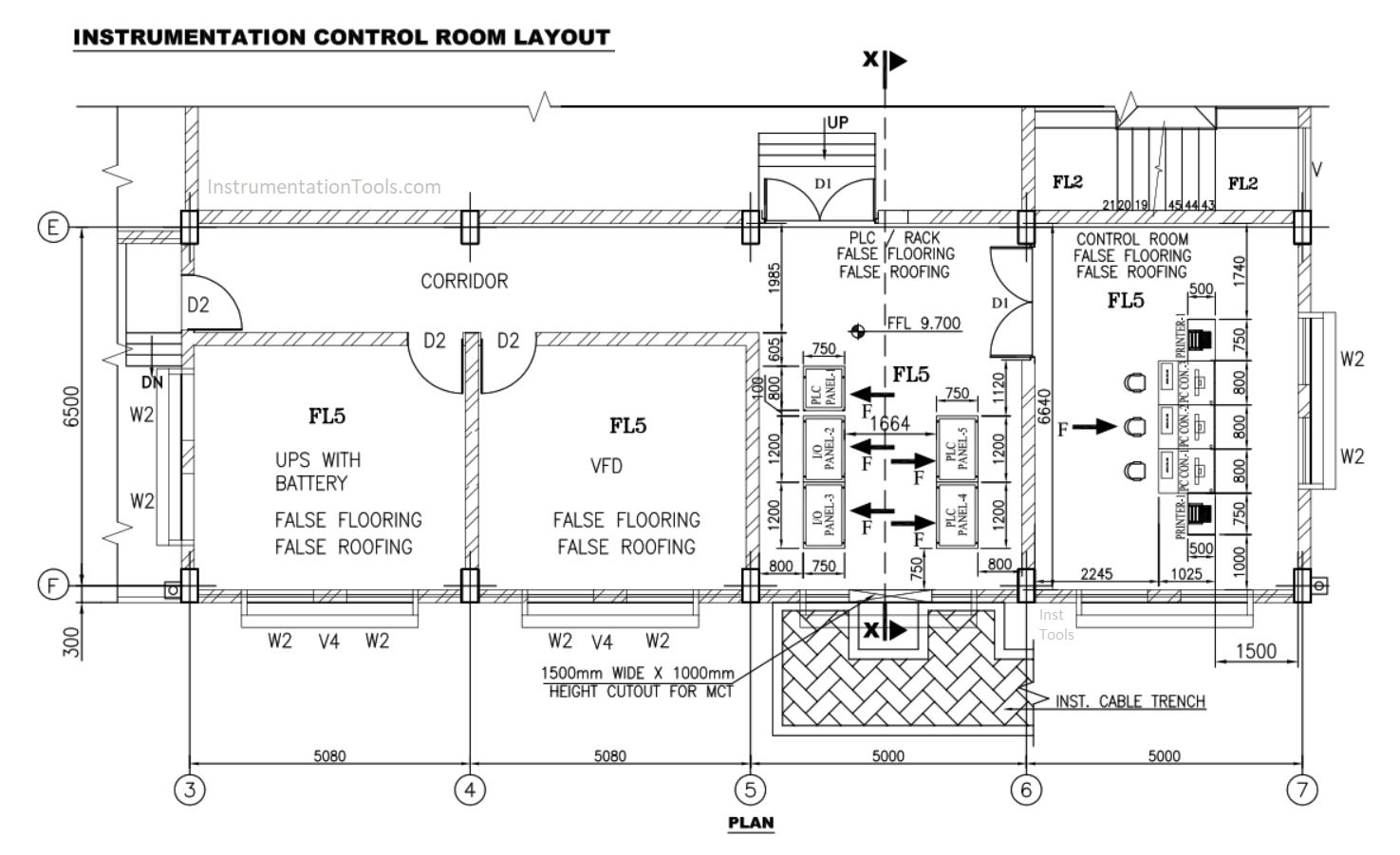
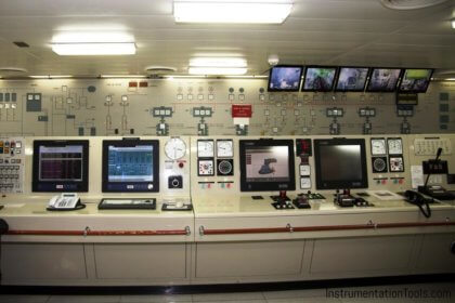
Control Room Layout
Instrument Control Room Layout is one of the important document which gives the idea about location & dimension of different items in the control room.
The main data that must include in the Control Room Layout are;
- Dimension of the room
- Entry & Emergency Exit
- Ventilation & Windows
- Lighting arrangement
- Panel Dimension & Location
- Proper placement of operator console
- Cable entry
- Air-lock system
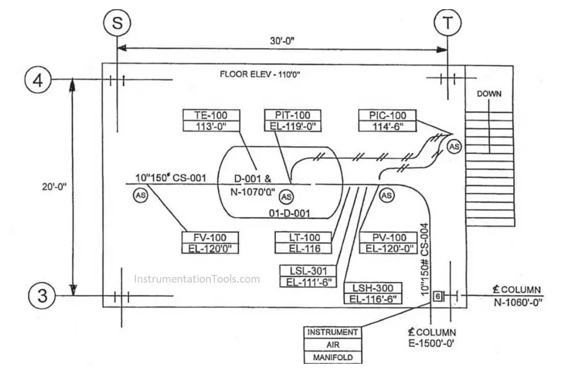
Instrument Location Layout
Instrument Location Layout is a document indicating the location & elevation of each instrument, in the plan view.
It gives the location information of the instrument and also to which junction box/air header it is connected.
Instruments mounted on equipment are also shown in this layout with the help of the equipment layout.
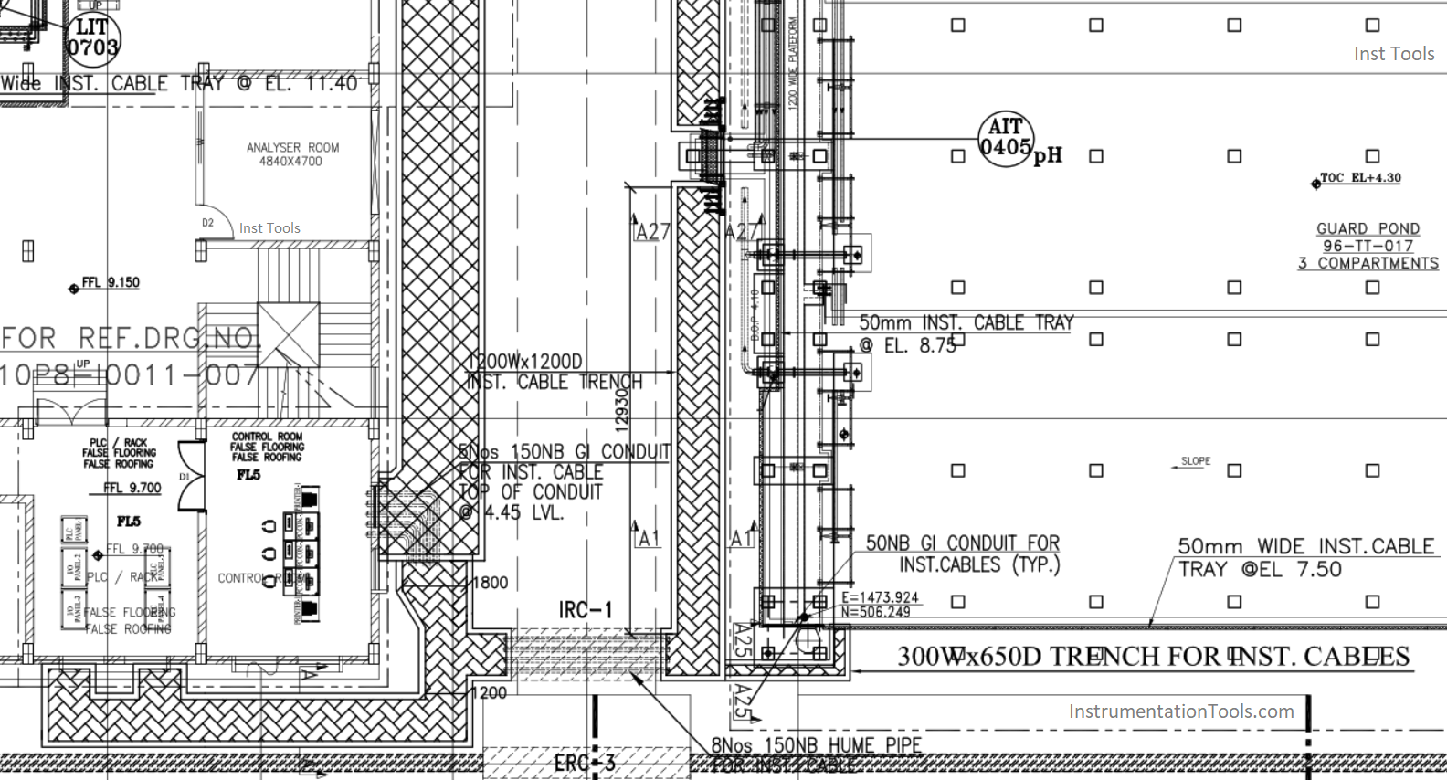
Instrument Tray Layout
Instrument Tray Layout is the drawing that shows the location of junction boxes, instrument air header, local panel & the instrument tray routing in the plan view.
They are made with the guidelines of Instrument Location Layout and thus helps in grouping junction boxes & air headers.
They also show the elevation & number of trays running in tiers in cross-sectional view.
Instrument Tray Layouts are mainly made to show all instrument-related items mounted in the field and are connected to the control room by multicore cables running on instrument trays.
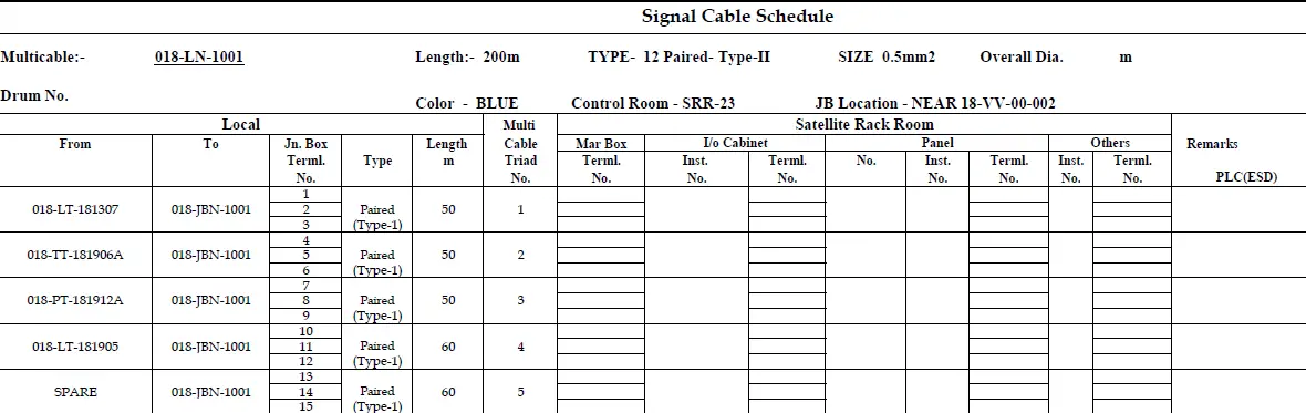
Instrument Cable Schedule
A cable Schedule is a document that contains the list of instrument cables.
Each cable should have a precise number according to the numbering scheme.
It is the most important document used for cable laying purpose in project engineering
The main data include in Cable Schedule is as follows.
- Cable Number
- Cable Connectivity
- Type of Cable
- Length of Cable
- Size of Cable
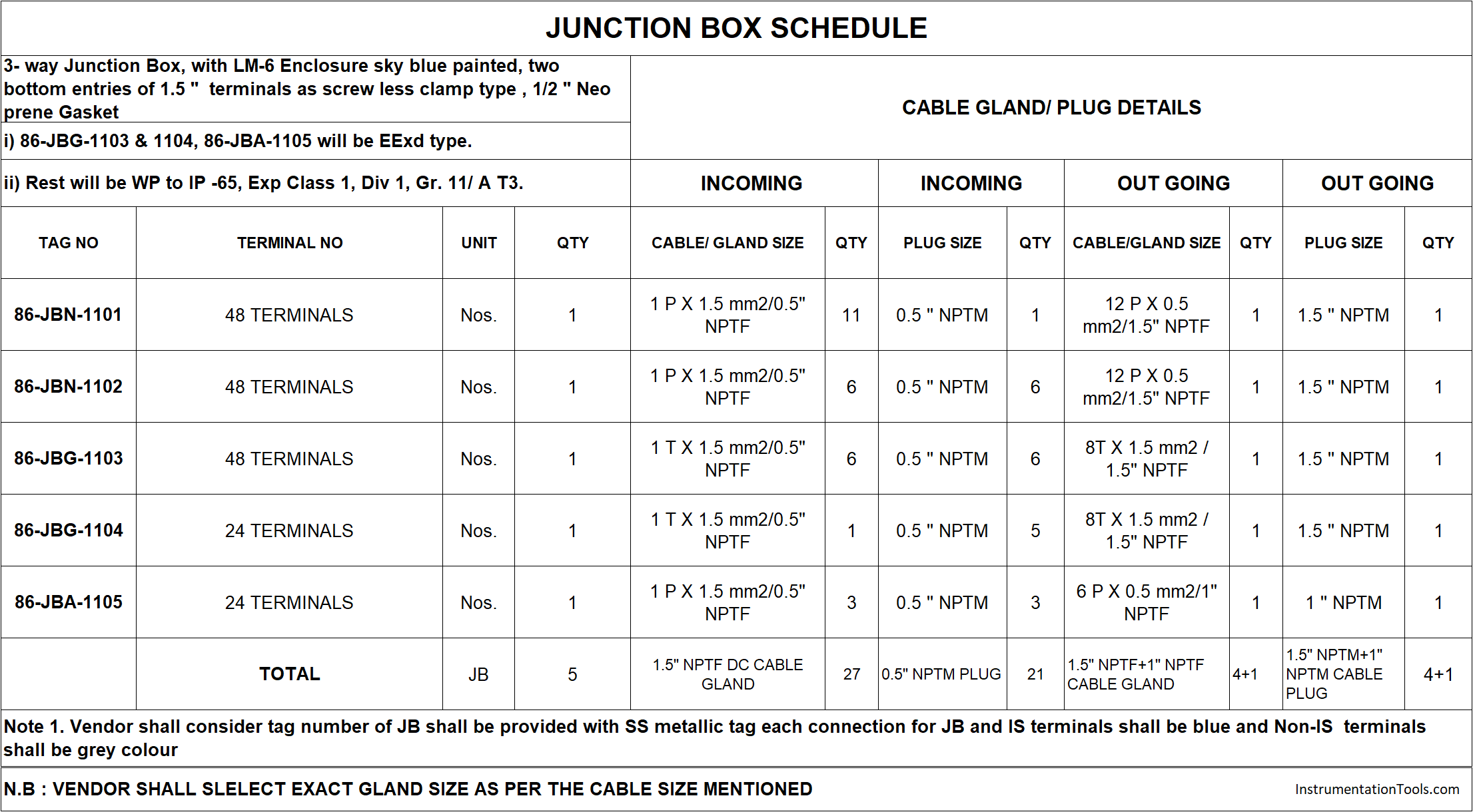
Instrument Junction Box Schedule
Instrument Junction Box Schedule is the document that shows all details of the junction boxes information.
Junction Box sizing is mainly dependent on Instrument Junction Box Schedule
The main data that must include in JB Schedule is as follows.
- Junction Box Number
- Type of Junction Box
- Area of Location
- Instruments Connected
- Terminal Details
Instrument Air Header Schedule
Instrument Air Header Schedule is the document that shows all details of the instrument air header and manifolds.
It also shows the air supply route to Instruments.
The main data that must include in Instrument Air Header Schedule is as follows.
- Instrument Air Header Number
- Type of Instrument Air Header
- Area of Location
- Instruments Connected
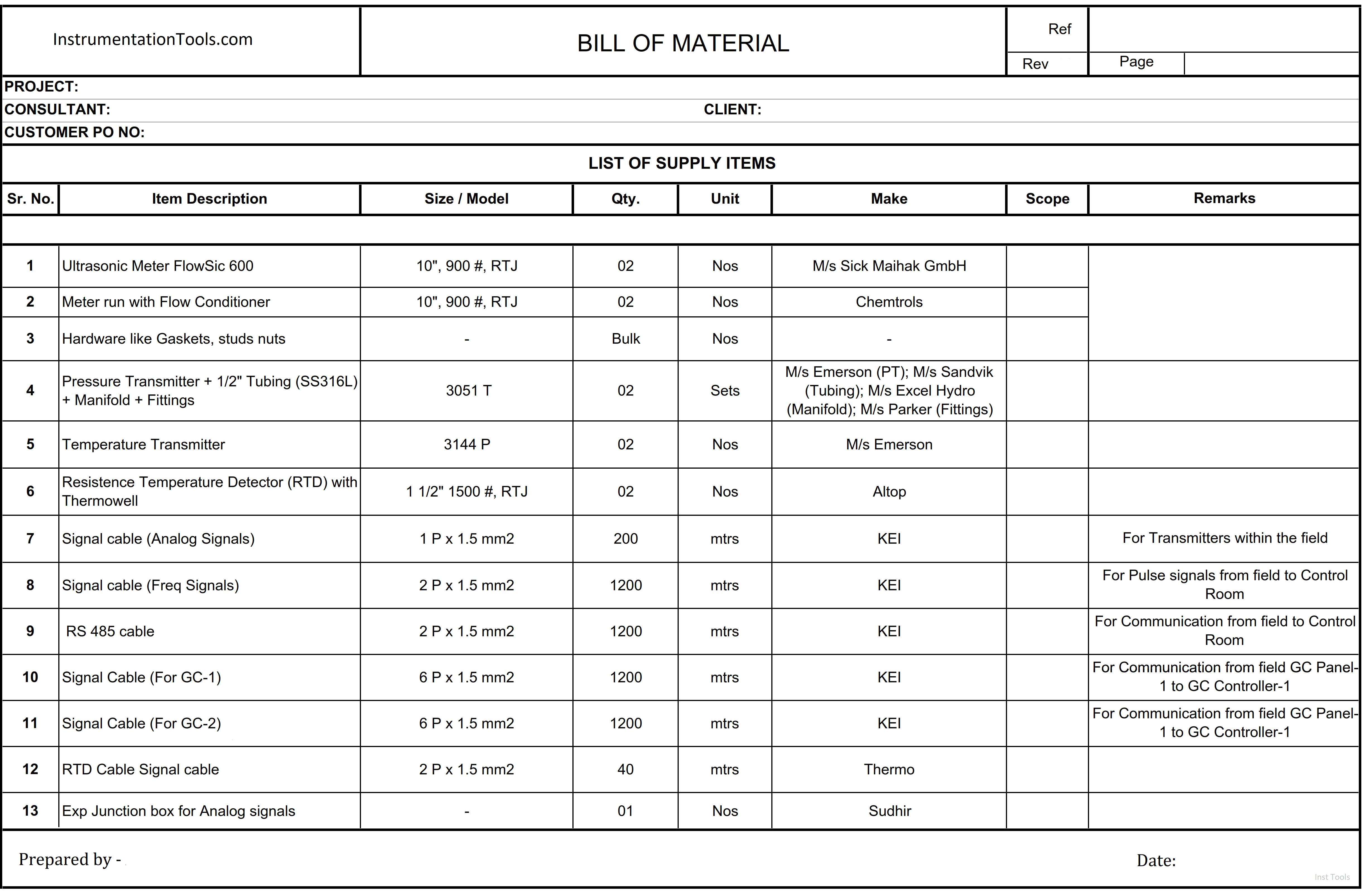
Instrument Bill of Material
The main purpose of the Instrument Bill of Material is to quantify various items required for project engineering.
It shows all materials and their costs that are required for project engineering and helps to calculate the budget of the project.
Instrument BOM is the document that mainly covers cable trays, junction boxes, tubes, pipes & fittings, air headers, cable glands, hook-up materials, stanchions, steel required for erection purposes.
The main data must include in Instrument BOM is as follows.
- Item Description
- Size of the Item
- Material of the Item
- Number of Quantities Required
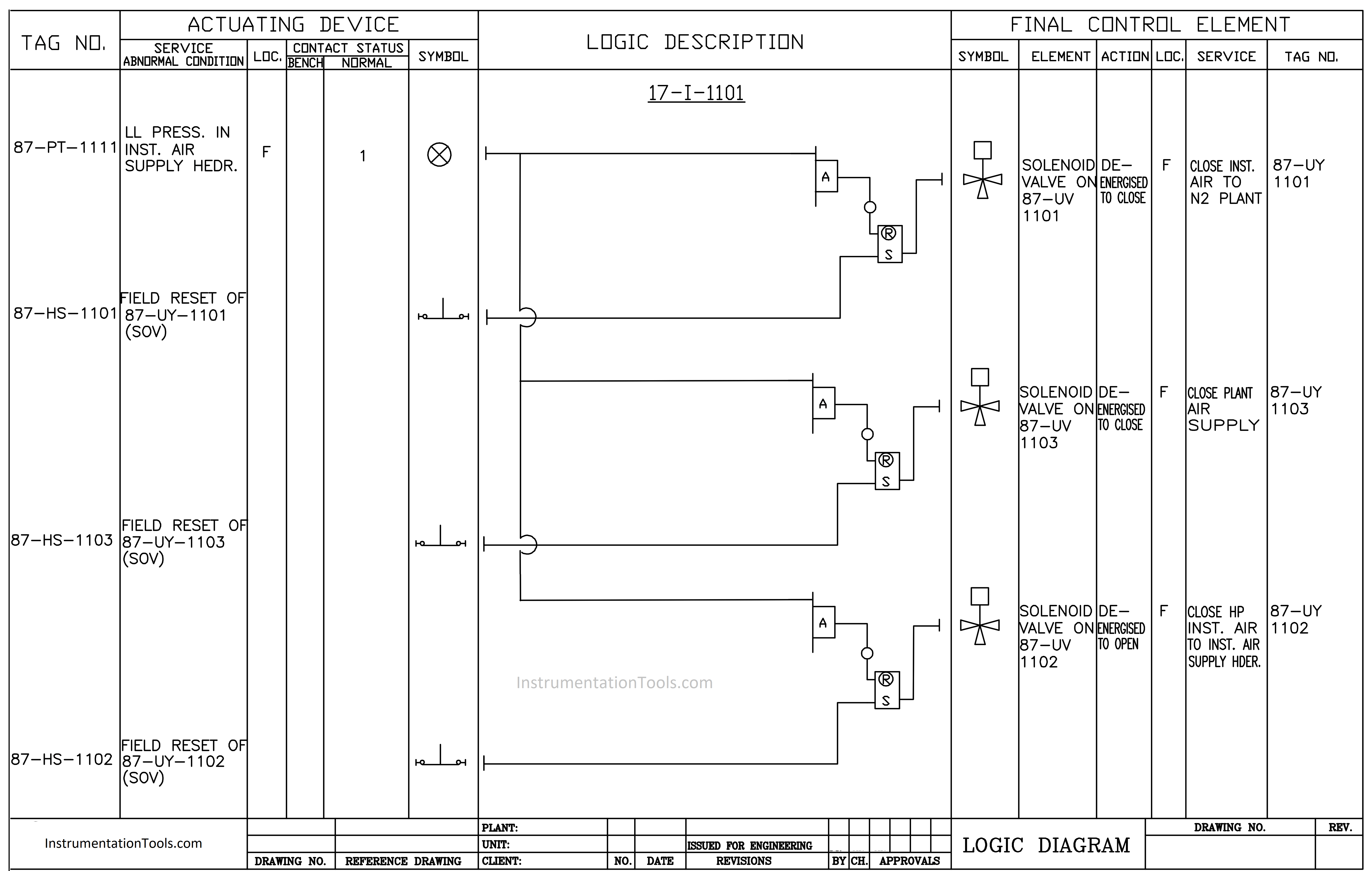
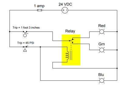
Instrument Logic Diagrams
The major function of the Instrument Logic Diagram is to determine the operation of a given component or system as the various input signals change.
The most common use of Logic Diagram is to provide a simplified functional representation of an electrical circuit.
It is easier and faster to figure out how output functions and responds to various input signals by representing a circuit using logic symbols than using the electrical schematic with its complex relays and contacts.
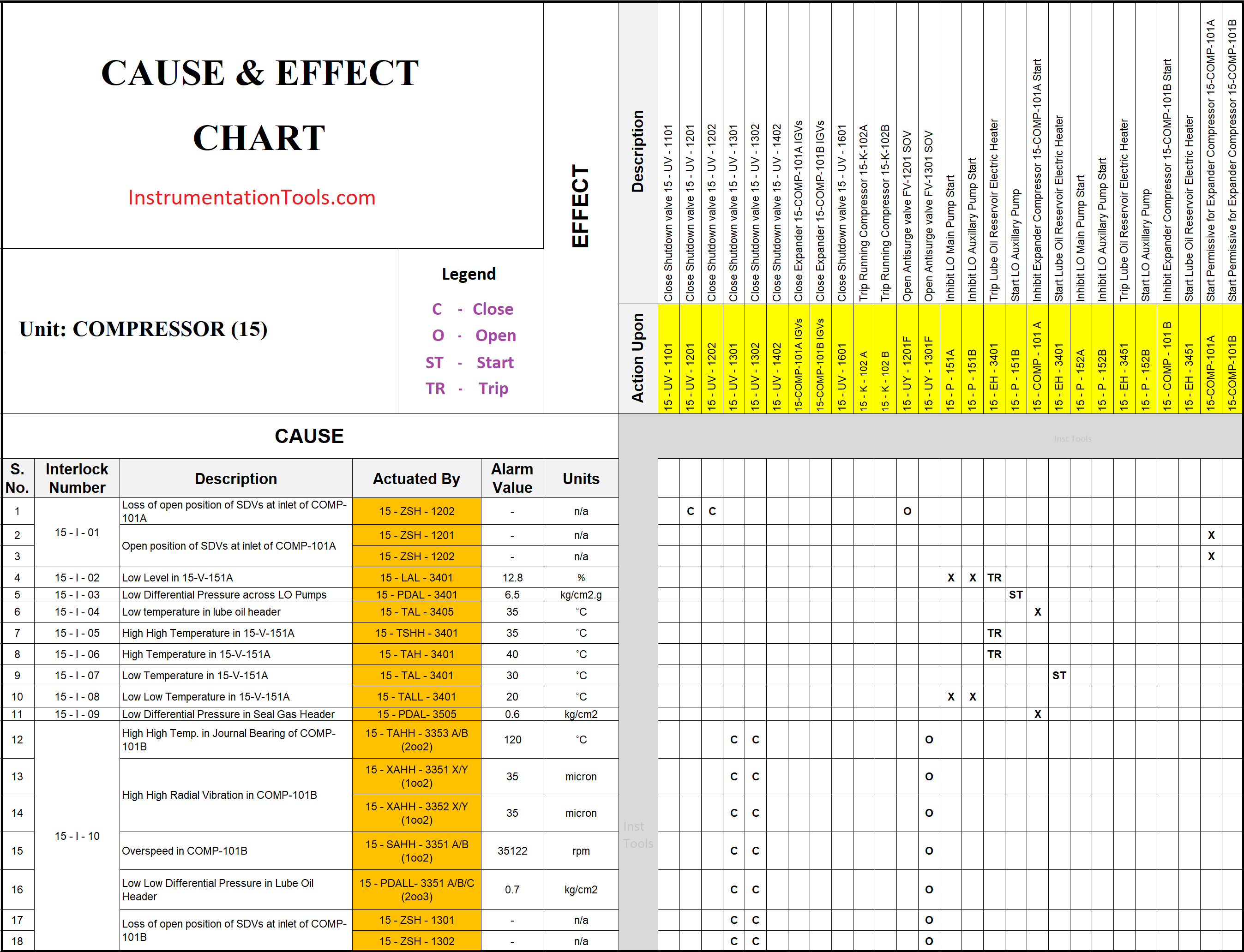
Cause & Effect Diagrams
Instrument Cause & Effect Document is a tabular chart of functions of various instruments.
This document indicates the cause as an instrument signal in one condition and its effects on other instruments connected in the loop as per the logic.
Did anything miss from the above list? Share with us through the below comments section.
Author: Greeshmesh TP
If you liked this article, then please subscribe to our YouTube Channel for Instrumentation, Electrical, PLC, and SCADA video tutorials.
You can also follow us on Facebook and Twitter to receive daily updates.
Read Next:


Alarm and trip settings is another document which normally instrumentation team deliver, which I found missing in the list….Worth noting that, certain organizations does not have individual index and I/O list, rather a single document.
sir can you share how to make cause and effect chart
I will wish to hv soft copy of ua hi books,what s the cost?
Excellent sharing. Would like to know more on open and close loop check commissioning with respect to DCS system I/O modules, input /output modules, SDS system etc…
Turn over acceptance test after commissioning…. etc Thank you.
Thanks to the Author: Greeshmesh TP a full project
Miss an overall connection diagram indicating interconnection between different system such as Fire&Gas, Analyser Systems, ESD system, DCS system etc.
Missing further is the DCS Functional Block Disgram indicating all aspects of control system which is the basic document for DCS configuration.
MTO is missing it seems
Very professional, Very useful to one and all of the instrumentation professionals
Sir you have kind heart and broad minded and I have no words to describe
Regards
Thank you so much for sharing the list.
Are all documents of this list developed in Basic Design stage?
Which of them are developed only in Detailed Design?
And could you send the PDF file of this list to my email address please?
OP, Thank you for this article. It helpful for me to justify to Management when I want to put drawings and documents together for a project and they do not want to pay for it.
I would add several documents to your list:
1) I would modify the Instrument Cable Schedule to be the Instrument Conduit & Cable Plan and Instrument Conduit & Cable Schedule
2) I would add a “Process Control Narrative” which is a textual description all of the analog control loops and the more complicated discrete loops, e.g., those with a Truth Table.
3) This is actually part of the electrical power drawing set, but it’s use would be required in instrument design, and that would be the Hazardous Area Electrical Classification Plan (HAEC).
4) Very important would be a controls network topology diagram that depicts the all of the devices on the network including power supplies, types of cables, and mode of communication.
Fantastic
level sketch?