This post provides information about basics of Trip, Interlock, Permissive and Sequences which are regularly used in instrumentation control systems like ESD, DCS, PLC etc.
Trip:
The term Trip refers to an action that is initiated by the control system and which forces a device or devices to a pre-determined state.
Example of Trip Signals: Close Valve, Open Valve, Stop motor, etc.
The Safety Instrument System (SIS) or a Hardwired systems normally initiate trips, however the PLCs or DCS may also initiate trips provided the necessary independence and SIL ratings are met.
Once a device or devices have been forced to a pre-determined state by the action of a Trip they will remain in that state until the Trip is manually reset by a conscious operator action.
For example:
- High level in a vessel initiates a trip system which stops the pump feeding that vessel, the pump will remain stopped even if the level in the vessel falls to a safe level.
- The Trip must be ‘reset’ by the operator before the pump can be re-started.
- The Trip can only be ‘reset’ if the level in the tank has fallen to a safe level.
- Resetting the Trip will not cause the pump to automatically re-start, however it may be re-started by an operator action or a control system command e.g. part of a sequence.
The resetting of Trips is a controlled procedure which will only be possible if the operator is logged in and has the necessary access rights.
Under normal circumstances it shall not be possible to ‘override’ or `defeat’ Trips.
Interlock:
An Interlock is in essence a ‘self resetting’ Trip. Interlocks are not deemed safety related and can be used for on/off control.
Interlocks are normally initiated by the DCS or PLCs, however if an Interlock is deemed to be safety related it may, depending upon SIL rating, be implemented in the SIS or a Hardwired system.
An interlock will force a device or devices to a pre-determined state e.g. Close valve, stop motor, etc.
Once a device or devices have been forced to a pre-determined state by the action of an Interlock they will remain in that state until the initiating cause returns to a ‘healthy’ condition, the Interlock will then be automatically removed.
Under normal circumstances it shall be possible to ‘override’ Interlocks for operational reasons or ‘defeat’ them for maintenance or other reasons.
Permissive:
A Permissive is a patricular type of Interlock used to prevent actions taking place until pre-defined criteria have been satisfied, for example prevents a pump starting until the suction valve is open.
Permissives are normally initiated by the DCS or PLCs, however if a Permissive is deemed to be safety related it may, depending upon SIL rating, be implemented in the SIS or a Hardwired system.
Once a Permissive has been satisfied and the resulting action implemented it becomes inactive, for example once the suction valve has been opened and the pump started the Permissive takes no further action, even if the suction valve is closed while the pump is running.
Under normal circumstances it shall be possible to ‘override’ Permissives for operational reasons or ‘defeat’ them for maintenance or other reasons.
Sequence:
A Sequence is defined as a pre arranged action or number of actions which are carried out by the control system. Sequences may be initiated by an event or operator actions.
Sequences may be ‘single pass’ or ‘cyclic’.
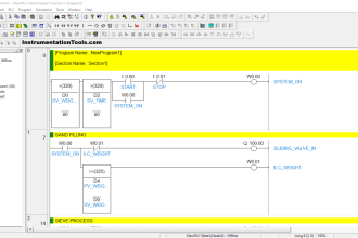
The following is an example of a ‘single pass’ sequence:
An agitated vessel reaches a pre-determined level. The operator initiates a sequence that carries out the following actions:
- Stop the feed pump
- Close the filling valve
- Stop the agitator.
- Wait 30 seconds.
- Open the discharge valve.
The following is an example of a ‘cyclic’ sequence:
- Low level in a vessel opens the filling valve.
- The valve remains open until high level is detected.
- On high level the valve closes.
- The valve remains closed until low level is detected.
- On low level the valve opens and the sequence it repeated.
Combined Functions:
It is common for Trip, Interlock, Permissive and Sequences to fulfill combined functions, for example the following pump protection system illustrates how the same system can perform various functions.
Permissive
Prevent pump starting until suction valve is open.
Prevent pump starting until suction valve is open.
Interlock
Pump running – suction valve closed-pump stops.
Pump running – suction valve closed-pump stops.
Sequence
High level in vessel-Pump stops
Low level in vessel-Pump starts.
Pump running – suction valve closed – pump stops,
Suction valve re-opened – pump remains stopped.
Operator resets trip.
Pump available for re-start.
High level in vessel-Pump stops
Low level in vessel-Pump starts.
Pump running – suction valve closed – pump stops,
Suction valve re-opened – pump remains stopped.
Operator resets trip.
Pump available for re-start.
Also Read: How to tune a PID Controller


how to calculate orifice plate flow measurement
good
Permissive start how it related to SIL and SIS
this web page give excellent technical information about I&C oriented…really very useful……
everyone must be use this webpage for more technical updates…..
Excellent goods from you, man. I’ve understand your stuff previous to and you are just extremely wonderful. I really like what you’ve acquired here, really like what you’re saying and the way in which you say it. You make it entertaining and you still take care of to keep it wise. I can not wait to read much more from you. This is actually a wonderful site.
Logic or programming in PLC is done using Ladder logic or other formats. In general there are some terms that are used is programming to identify how they will interact with other system.
These terms include:-
Permissives are minimum perquisites that are required for drive or system to operate. Like lubrication system should be on before a drive starts etc.
Protection prevent a drive or logic from a harmful condition and start/ stop system to prevent human or mechanical damage. Like high current will trip a motor to prevent damage. These code act without any checks for permissives as they are typically a last resort kind of stuff.
Lastly Interlocks are code or conditions that are execute when another action happens and change how the drive or code was working to provide a smooth running process.
Example :
For example if 2 motors (say motor A & motor B) are there and only one is generally used but necessary 24 x 7. Then I will add an interlock in logic of motor A that if the other motor B turns off due to error then start drive A.
Interlocks are often used to start auxiliary equipment, standby drives, or to prevent starting of systems for smooth operations.
A key note is that Interlocks will require permissives to be followed, that is only interlock is not sufficient the permissives are also to be met.
Interlocks do jobs that can be executed by operator action also but provide some ease in operation and reduce human error.
Reference – Quora
Need help with understanding to interlock 2 different kinds of safety systems? for example 1 System with PLd & SIL2 safety and another with a safety relay system.