Gestures, actions, sounds, and expressions tell us some information, and these are the ways of communicating with one another.
Similarly signal is a way of communicating by sending information from one system to another system. In other words, the signal is a function that represents information or data.
What is a Signal?
Signal is an electromagnetic wave that carries information through a physical medium. Here the data is converted into an electromagnetic signal either analog or digital and sent from sender to receiver.
Voltage and current are a few time-varying quantities that are used to represent data, by varying these quantities with respect to time data can be transmitted. Similarly, signal is also represented as the function of the frequency domain rather than the time domain.
For communicating between two systems, a message signal is passed through an encoder and modulator to transmit through a medium while it is passed through a decoder and demodulator to receive the message signal at the other end.
Signals are divided into two categories based on their nature.
Signals which are
- Signal that are Continuous as time-varying in nature are analog signals
- Signals which are discrete are called digital signals.
Analog Signals
Analog signal is a form of electrical energy (voltage, current, or electromagnetic power) for which there is a linear relationship between electrical quantity and the value that the signal represents.
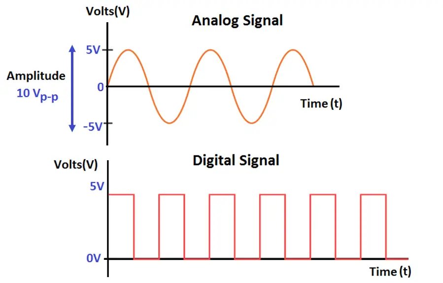
The signal whose amplitude takes any value in a continuous range is called an analog signal.
Analog Signals are continuous in nature which vary with respect to time. They can be periodic or non-periodic.
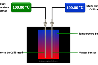
Voltage, current, frequency, pressure, sound, light, and temperature are the physical variables that are measured with respect to their changes with respect to time to obtain information.
When the voltage versus time graph is plotted we see a curve with continuous values like sine waves.
These signals are more subjected to noise as they travel through the medium, these noises result in information loss in the signal.
Analog to digital converter converts analog signal to digital signal by a process called sampling and quantization. Sound waves are converted to a sequence of samples by the process of Sampling
Examples of Analog Signals
Conventional (old) transmitters, transducers convey data in analog mode.
The signals include audio signals transmitted through wires, video signals broadcasted using older technology, radio signals, and analog watches.
Digital Signals
The signal, whose amplitude takes only limited values is called a Digital signal.
Digital signals are discrete, they contain only distinct values.
Digital signals carry binary data i.e. 0 or 1 in the form of bits, it can only contain one value at a period of time. Digital signals are represented as square waves or clock signals.
The minimum value is 0 volts whereas the maximum value is 5 volts.
Digital signals are less subjected to noise compared to analog signals.
Transmission of digital data in the analog channel is done by a process called Modulation.
Amplitude modulation is a process in which digital data is converted to analog signals using a single frequency carrier signal. Similarly, FREQUENCY shift keying uses a constant amplitude carrier signal and two frequencies to differentiate between 1 and 0.
Nowadays usage of digital signals for transmitting information has increased rapidly in every field of usage as the applications and properties of digital signals are more productive compared to analog signals.
Examples of Digital Signals
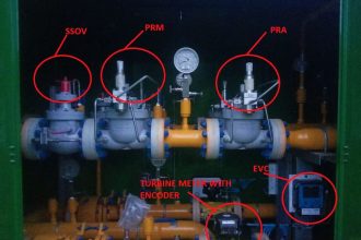
- Smart transmitters using various protocols transmit data through analog and digital signals.
- Digital watches.
- Digital video signals.
- CD’s.
- DVD’s.
- Computer.
Difference between Analog and Digital Signals
| Analog Signals | Digital Signals |
| Analog signal is continuous and time varying. | Digital signal have two or more states and in binary form. |
| Troubleshooting of analog signals are difficult. | Troubleshooting of digital signals are easy. |
| An analog signal is usually in the form of sine wave. | An digital signal is usually in the form of square wave. |
| Easily affected by the noise. | These are stable and less prone to noise. |
| Analog signals use continous values to represent the data. | Digital signals use discrete values to represent the data. |
| Accuracy of the analog signals may be affected by noise. | Accuracy of the digital signals are immune from the noise. |
| Analog signals may be affected during data transmission. | Digital signals are not affacted during data transmission. |
| Analog signals use more power. | Digital signals use less power. |
| Examples: Temperature, Pressure, Flow measurements, etc. | Examples: Valve Feedback, Motor Start, Trip, etc. |
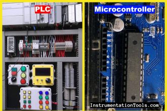
| Components like resistors, Capacitors, Inductors, Diodes are used in analog circuits. | Components like transistors, logic gates, and micro-controllers are used in Digital circuits. |
If you liked this article, then please subscribe to our YouTube Channel for Instrumentation, Electrical, PLC, and SCADA video tutorials.
You can also follow us on Facebook and Twitter to receive daily updates.
Read Next:
- History of Microprocessors
- History of 4 to 20 mA signals
- PLC Controllers History
- What is a Network?
- Early Vacuum Tube History


Hi,
The article looks more academic than industry-related. Why not provide details regarding 4 – 20 mA, the necessity of a live-zero in current loops, analog signals based on HART, effects of EMI and shielding, 2, 3 and 4-wire signal and power transmission etc.
On the digital front, we can have explanations as to why 24 Vdc is widely prevalent in the industry, devices utilizing this mode of communication, concepts of Overall and Individual shielding – why the former is the selected construction mechanism for digital cables, etc.
Thanks