Instrument Hook Up Diagram is also called Installation drawing, specifies the scope of work between Mechanical and Instrumentation departments.
It is a detailed drawing showing typical installation of an instrument in a correct manner so that the instrument operates properly and prevent issues which could potentially affect the measurement such as liquid trap in gas impulse.
Instrumentation Construction Engineer has to review and verify certain important points before going for an Instrument erection.
- Check Tag No of particular instrument or list of instruments.
- Scope of work between mechanical and instrumentation.
- Bill of material such as SS fittings, Tubing, Isolation valves, plugs, manifold block, Transmitter bracket mounting type (Vertical or Horizontal) mounting bracket type,
- Check for bulk material for each installation
- Type of material to use to measure based on fluid and its parameters.
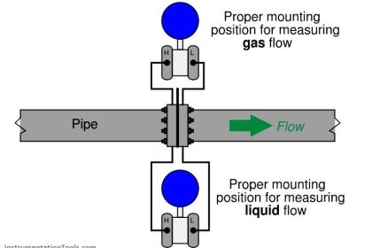
- Position of instrument in reference to process tapping point.
- The tubing slopes need to be paid attention.
Instrument Hook Up Diagram
Instrument Hook Up Diagrams detail the accessory and tubing hookup for both process and field instruments based on the tag number.
It should include standard specifications for the welding of hook-up piping, heat tracing & insulation and pressure testing & painting requirements.
Generally included are;
-
Tag number
-
Numbers of the loop drawing.
-
Layout & routing drawing and isometric piping drawing containing the particular control loop component.
-
Elevations of both the primary control loop component and process connection.
-
Tagging of mechanical (piping or equipment) to instrumentation interface
-
Tagging of all elements/fittings & valves with item numbers.
-
Direction of slopes in hook-up lines.
-
Elevation of Instrument.
-
Maximum allowable lengths of hook-up lines.
-
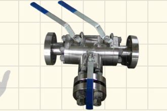
Accessories often detailed include Mono-flanges, Double Block and Bleed Valves and Fittings etc.
-
Material take off with part numbers, number of particular fittings, size, connection, material type, mounting type.
-
weather shield and tubing specification.
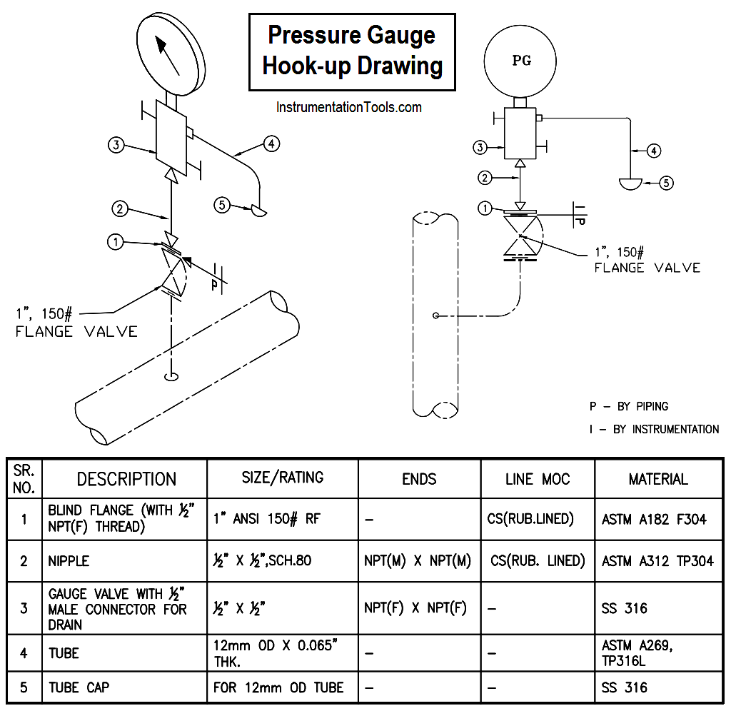
Hook-up for Pressure Gauge
The below diagram shows the required components and tubing for installation of a pressure gauge. The required parts are shown in the below table.
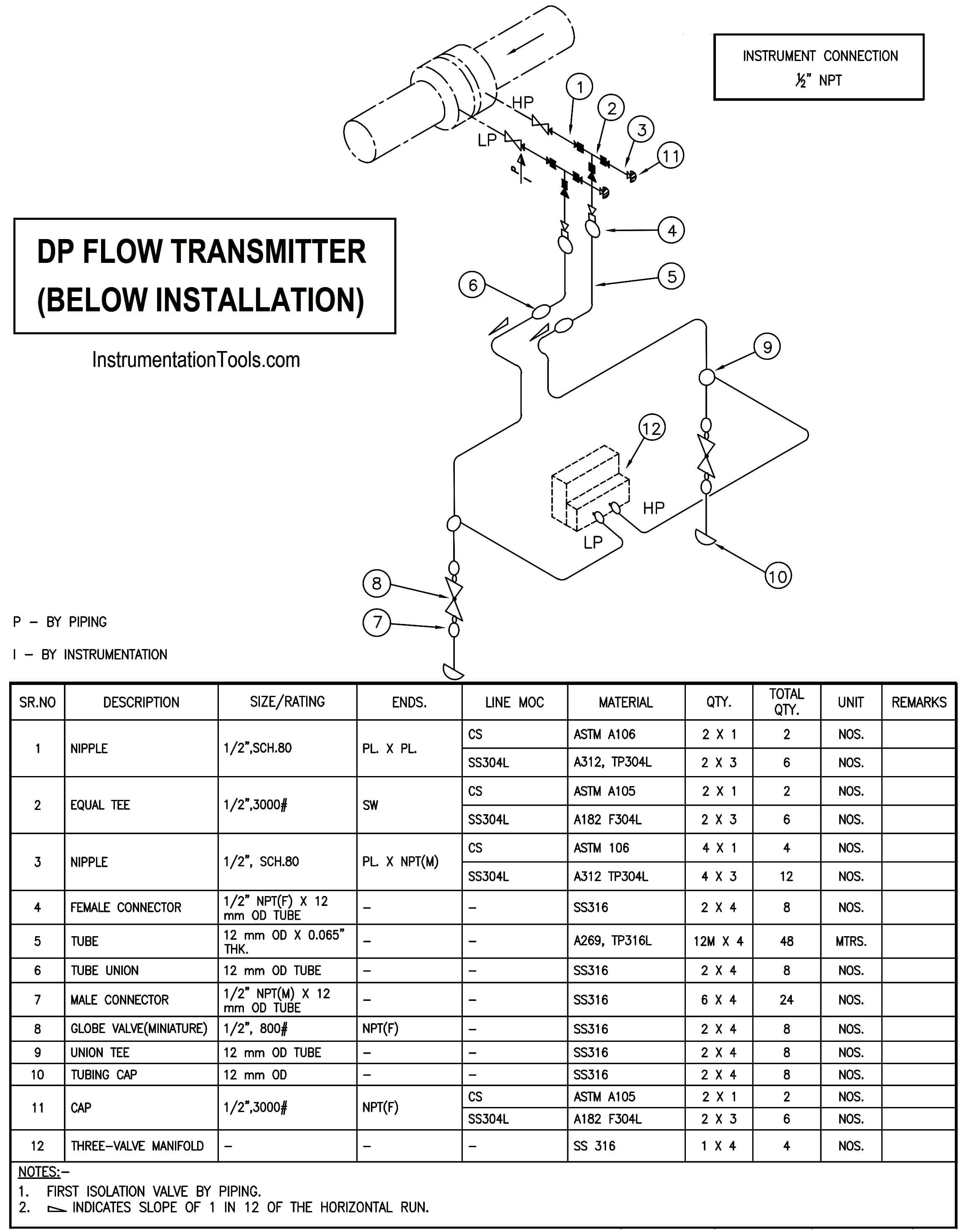
Hook-up for Differential Pressure Transmitter
The below diagram shows the required components and tubing for installation of a differential pressure transmitter (installed below the tapping point). The required parts are shown in the below table.
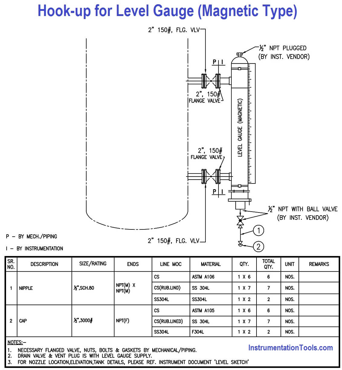
Hook-up diagram for Level gauge
The below diagram shows the required components and tubing for installation of a level gauge. The required parts are shown in the below table.
Read Next:
- How a Process Control Loop Works
- Instruments Calibration Procedures
- Factors for Thermocouple Selection
- Instrumentation Loop Diagrams
- PLC Multiple Choice Questions