A Residual Current Circuit Breaker (RCCB) is a key safety measure when it comes to the protection of electrical circuits.
It is a leakage current sensing device, which can automatically measure and disconnect the circuit whenever a fault occurs in the associated circuit or the current exceeds the rated sensitivity.
In RCCB, the ON and OFF positions are visible in its window, Green color indicates the OFF position, Red color indicates the ON position.
MCB versus RCCB
The difference between RCCB and MCB is that RCCB will have a test trip button and MCB does not have it.
Purpose: Aimed at protecting an individual from the risk of electric shocks as well as electrocution, RCCB is particularly helpful in occurrences of a sudden earth fault. The presence of RCCB ensures that in such cases, the circuit will trip instantly and the person is thus protected to remain safe from an electric shock.
Residual Current Circuit Breaker
RCCB works based on the principle of Kirchhoff’s current law. The law states that the incoming current must be equal to the outgoing current in a circuit.
RCCB thus differentiates the deviation in current values between live and neutral wires. In principle, the current flowing to the circuit from the live wire should be the same as that flowing through the neutral wire.
In case of a fault, the current from the neutral wire is gets reduced, the differential between the two is known as Residual Current. Upon spotting a Residual Current, the RCCB is triggered to trip off the circuit.
Internal Parts of RCCB
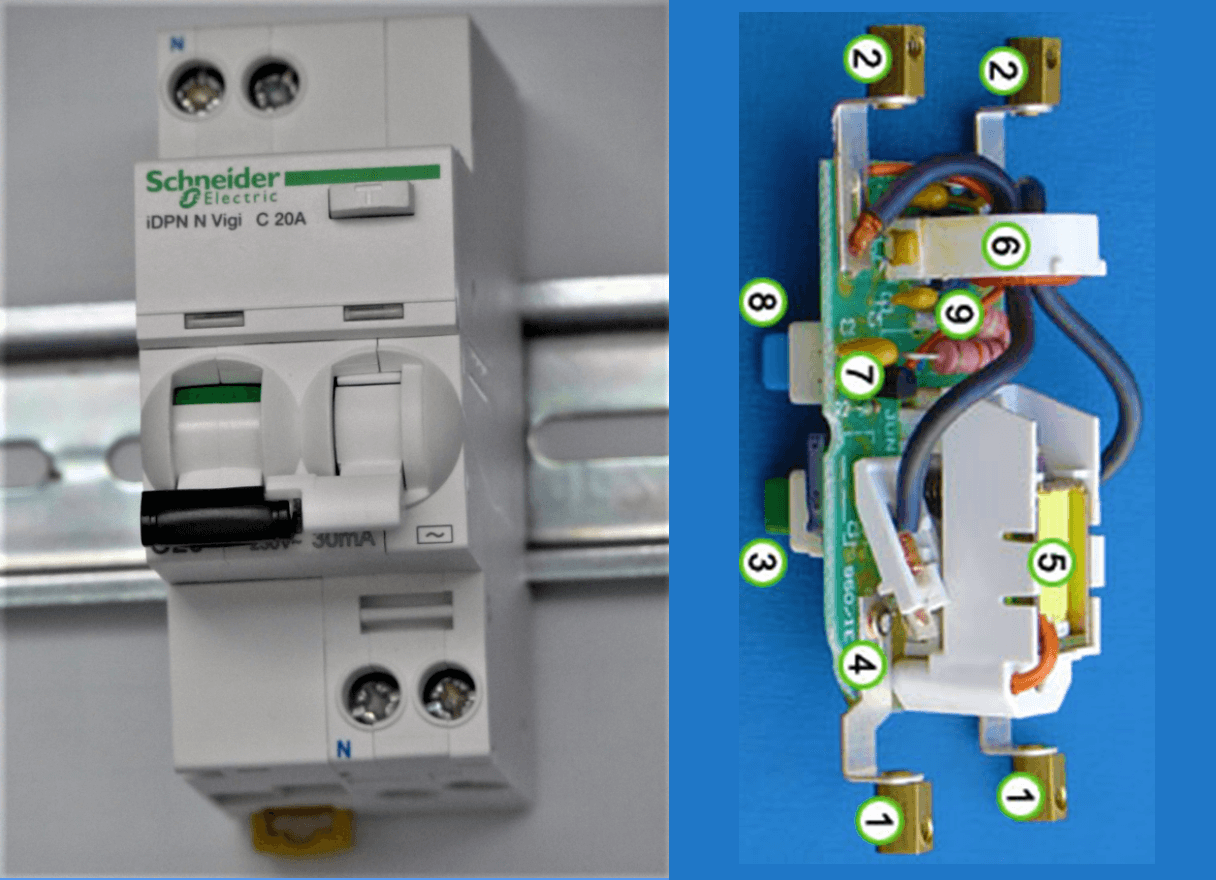
The above photo (right side) shows the internal parts of the electrical Residual-Current Circuit Breaker.
- incoming terminals
- outgoing terminals
- reset button
- contact
- solenoid
- sense coil
- sense circuitry
- test button
- test wire
The incoming supply and the neutral conductors are connected to the terminals at (1) and the outgoing load conductors are connected to the terminals at (2). The earth conductor (not shown) is connected through from supply to load uninterrupted.
When the reset button (3) is pressed the contacts ((4) and hidden behind (5)) close, allowing current to pass. The solenoid (5) keeps the contacts closed when the reset button is released.
The sense coil (6) is a differential current transformer that surrounds (but is not electrically connected to) the live and neutral conductors. In normal operation, all the current down the live conductor returns up the neutral conductor. The currents in the two conductors are therefore equal and opposite and cancel each other out.
Any fault to earth (for example caused by a person touching a live component in the attached appliance) causes some of the current to take a different return path which means there is an imbalance (difference) in the current in the two conductors (single-phase case), or, more generally, a nonzero-sum of currents from among various conductors (for example, three-phase conductors and one neutral conductor).
This difference causes a current in the sense coil (6) which is picked up by the sense circuitry (7). The sense circuitry then removes power from the solenoid (5) and the contacts (4) are forced apart by a spring, cutting off the electricity supply to the appliance.
The device is designed so that the current is interrupted in a fraction of a second, greatly reducing the chances of a dangerous electric shock being received.
The test button (8) allows the correct operation of the device to be verified by passing a small current through the orange test wire (9). This simulates a fault by creating an imbalance in the sense coil. If the RCD does not trip when this button is pressed then the device must be replaced.
Sensitivity of RCCB
A human being is comfortable with an electric shock to the extent of 30 mA. While up to 10mA may just evoke a tingling sensation, 10mA onwards may lead to muscular contraction, further leading to a respiratory paralysis at around 30 mA.
RCCBs are therefore designed and developed to look for small changes in residual current. In cases where protection from fire hazards is sought, RCCB s are also used to track higher changes in residual current of up to 311mA.
Classification of RCCB
Based on the type of poles in RCCB
- 2 Pole RCCB
- 3 Pole RCCB.
- 4 Pole RCCB.
2 Pole RCCB
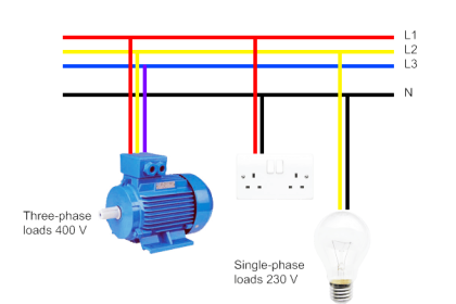
It is used in a single-phase supply connection that has only a live and a neutral wire.
3 Pole RCCB
It is used in three wires of a three-phase supply connection.
4 Pole RCCB
This is used in a three-phase supply connection, neutral of supply.
Rating from 10 Amp….100 Amp
Sensitivity 30, 100, 300 mA.
Advantages
- Provides safety and protection against earth fault as well as any leakage current
- Automatically disconnects the circuit when the rated sensitivity is gone beyond.
- Provides dual termination option for both cable and busbar connections.
- Provides protection against voltage fluctuation as it includes a filtering device that guards against a momentary change of voltage levels.
Disadvantages
RCCB has some limitations also.
- RCCB does not guarantee to function if none standard waveforms such as half-wave rectified or pulsating dc are generated by loads. This is primarily because RCCB is designed to operate on normal supply waveforms.
- There might be some unwanted tipping of RCCB. The main reason is whenever there are sudden changes in electrical load, there can be small current flow to earth, especially in the old appliances.
- RCCB does not protect from current overload. It has been designed to protect when the difference between live current and neutral current is different. However, a current overload cannot be detected.
- RCCB does not protect against line-neutral shocks. This is mainly because the current in them is balanced. The current gets balanced as both terminals are held jointly together.
- RCCB does not protect from the overheating that strike if cable conductors are not properly screwed or properly tightened at the terminals.
Applications
RCCB is highly important in providing real-time protection for circuits in industries and high voltage commercial setups especially, its importance cannot be undermined as there is always the risk of shocks and accidental deaths on account of it.
Reference: Wikipedia
Read Next:
- Circuit Breaker Quiz
- Circuit Breaker Animation
- Oil Circuit Breakers
- How to Select a Fuse?
- What is Auto Reclosing?