Vortex shedding
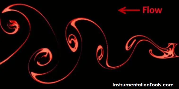
Fig: Color enhanced smoke trail showing von Karman Vortex Street in laminar fluid flow
Vortex Shedding effects on Multiple Thermowell Installations
Thermowells are essentially a circular cylinder installed like a cantilever into the process piping. They provide process condition protection and a process seal for temperature sensors. As a process fluid passes around the thermowell, low pressure vortices are created on the downstream side in laminar, turbulent, and transitional flow.
The combination of stresses, generated by the static and dynamic in-line drag forces from fluid flow and the dynamic transverse lift forces caused by the alternating vortex shedding, create the potential for fatigue-induced mechanical failures of the thermowell. Piping designers may use a variety of tools to predict and avoid thermowell failures in their systems, but ASME PTC 19.3 TW-2010 is the internationally recognized standard by which thermowells are designed.

Multi-thermowell installations
Process designers occasionally specify the installation of multiple thermowells for redundancy or 2 out of 3 voting. If they are in close proximity to one another the fluid flow between them is altered. Since ASME PTC 19.3 TW-2010 covers only single thermowell installations, the PTC refers the designer to a portion of the ASME Boiler Pressure Vessel Code rather than deal with the complexity of the interactions between two or more thermowells in the flow.
While this reference provides design guidance for optimization of fluid flow over tube arrays, it leaves the designer without substantial guidance on the effects of the vortex shedding on either the upstream or downstream thermowells. To understand that, peer-reviewed journal articles showing experimental results must be referenced. These experiments cover a variety of cylinder arrays, but the two configurations most applicable to process control installations are “side-by-side” and “tandem”.
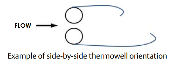
In side-by-side installations the velocity of the fluid increases as it passes between the two thermowells due to the constriction in the flow. With an increase in velocity comes an increase in the vortex shedding rate along with an increase in the forces acting on the thermowells. As the space between the thermowells increases, this effect is reduced.
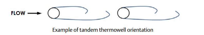
In tandem thermowell installations the trailing thermowell is either adjacent to or within the vortex street generated by the upstream thermowell. This changes the forces on the leading thermowells and induces additional forces on the trailing thermowell.
In the tandem orientation, only the forces are affected, not the shedding rate since the fluid velocity is unchanged. This means that if the thermowells are designed such that the vortex shedding rate is outside the in-line or transverse lock-in regions they may still be acceptable for use in a tandem installation..
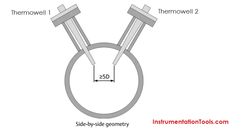
Much of the available experimental data is taken in the “close proximity” region (within 8 cylinder diameters) to generate the most dramatic results. To the process piping designer, the data suggest that when using two or more thermowells in conjunction with one another, the best thermowell installation orientation is side-by-side with at least 5 thermowell diameters spacing between them. However, the geometry of side-by-side installations can be difficult to fabricate and verify. This fact alone might cause the designer to consider tandem orientation.
If the designer chooses the tandem thermowell orientation (because it is easier to fabricate or because there is no other choice) then the spacing between the thermowells must be greater than the distance required for the vortex street to dissipate. This distance varies with fluid density and velocity, but the experimental results show vortices generally decay within 100 thermowell diameters. For typical thermowells of tip diameter 0.50 in. (12.7mm) or 0.75 in. (19.1mm), the center-to-center distance between thermowells would need to be anywhere from 4 to 6 feet (1200 to 1800mm).
Elbows or other in-situ flow disruptions help to dissipate vortices and can reduce the spacing requirements, however this is highly variable and should be evaluated on a case-by-case basis. In the end, only if the vortices can be dissipated through spacing or flow disruptions can the designer use ASME PTC 19.3 TW-2010 to evaluate the thermowell installation.
Article Source: EmersonProcess