The purpose of Instrumentation and Control (I&C) Design document is to cover the project-specific technical requirements which are to be followed throw-out the Feed or Detailed Engineering Phase while preparation of engineering deliverables.
Design Basis is considered as a mother document for all the engineering activities or deliverables to be carried out in a particular project.
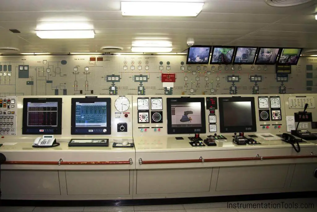
Instrumentation and Control Design
We will first understand the inputs required to prepare this document.
Inputs Required
Below listed references are the required inputs for the preparation of the document “Instrumentation & Control Design Basis”.
- Client’s Specification / Philosophy
- Electrical Hazardous Area Layout – Process Package
- Basic Engineering Design Data
Now let’s discuss the typical structure of the document.
Typical Structure of Design Basis of Instrumentation & Control
Instrumentation & Control Design Basis should cover below listed technical requirements as a minimum.
1. List of Codes, Standards, and Regulatory Requirements
2. Units of Measurements
3. Control System Philosophy
4. Package Control System Philosophy
5. Power Supply & Instrument Air Supply Philosophy
6. Hazardous Area Classification Requirements
7. Basic Requirements Related to Field Instruments and Cables
8. Basic Requirements Related to Installation & Related Items
9. Spare Philosophy
In this article, we shall talk about the first THREE points in detail.
List of Codes, Standards, and Regulatory Requirements
Standards:
Standard can define as a set of technical definitions and guidelines for designers and manufacturers. It provides all the necessary information/requirements for the product, service, and operation.
Written by the public organization or by the government body.
Examples: ANSI, API, ASTM, ISO, IEC, ISA, etc.
Codes:
Code can define as accepted general guidelines which use for design, fabrication, construction, and installation of equipment/instruments.
Written by Government or Government approved body.
Examples: ASME Boiler and Pressure Vessel Code, BS, DIN, etc.
Statutory & Regulatory Requirements:
Statutory Requirement:
Laws passed by a state and/or central government.
Regulatory Requirement:
The rule issued by a regulatory body appointed by a state and/or central government.”
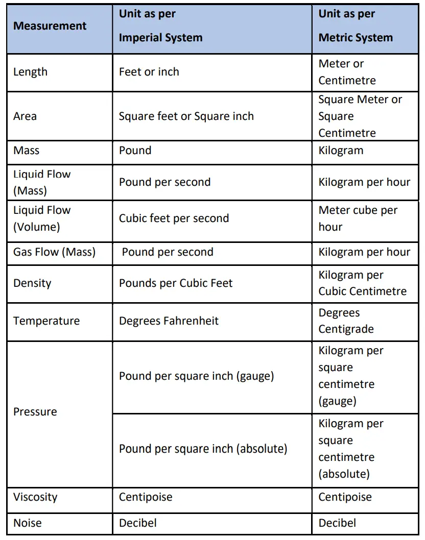
Units of Measurement
System for measuring unit either “Metric” or “Imperial” should be clearly identified in the I&C design basis with respect to the system follows in a country where plant to be build or as per requirement specified in the client’s specification/philosophy.
“Metric” system is generally preferred all over the world for units of measurement except the USA where the “Imperial” system is being followed.
Below is a sample illustration of Units. Quantum of details is change subject to the type of process variables to be measured.
Control System Philosophy
I&C design basis should cover the below-listed details/requirements as applicable for the control systems.
Mode of Plant Operation
Centralized
- For all process units
- For offsites
- For utilities
- Above all
Dedicated
- For each process units
- For offsites
- For utilities
- Above all
Type of Plant
- Grassroot
- Expansion / Revamping
- Modification
- Type of Control, Monitoring and Safety System
- DCS (Distributed Control System)
- SIS (Safety Instrument System) > SIL 3 system as per IEC 61511 or as per TUV AK6
- FGS (Fire and Gas System) > SIL 3 system as per IEC 61511 or as per TUV AK6
- MMS (Machine Monitoring System): For Rotating Package
- PLC for mechanical packages/small-process units
- Type of Controller Architecture (For Safety System – SIS and FGS)
- DMR (Dual modular redundancy): Mostly preferred
- TMR (Triple modular redundancy): Preferred for critical plants (Oil & Gas)
- QMR (Quadruple Modular redundancy): Not preferred due to high cost
Type of System Hardware Configuration
Simplex
Single processor, Single Power Supply, Single I/O card
Redundant
Redundant Processor, Redundant power supply and redundant I/O cards
Remote I/O Requirement
Generally preferred for MCC/VFD signal interface, where the distance between electrical sub-station building or Instrument equipment room is more.
The scan time requirement of the system
As per the client’s specification/philosophy. Generally, scan time is specifically requested for SIS (SIL 3) certified system which is less than 250 msec.
Type of Engineering Console Design
- Ergonomic
- Non-ergonomic
Auxiliary Console Requirement
Also Read: Instrumentation Guide
Package Control System Philosophy
I&C design basis should cover the below listed details/requirements as applicable for the package control system.
Package control by
- Plant main DCS and SIS
- PLC / other control system (Supplied by package vendor)
Type of package configuration
- Package skid with dedicated local control panel
- Package skid with junction boxes and without dedicated local control panel
- Package skid without junction box and local control panel
Type of communication between DCS and package control panel
- Hardwired Interface
- Serial communication (e.g. Modbus RS 485, 232, Modbus TCP/IP)
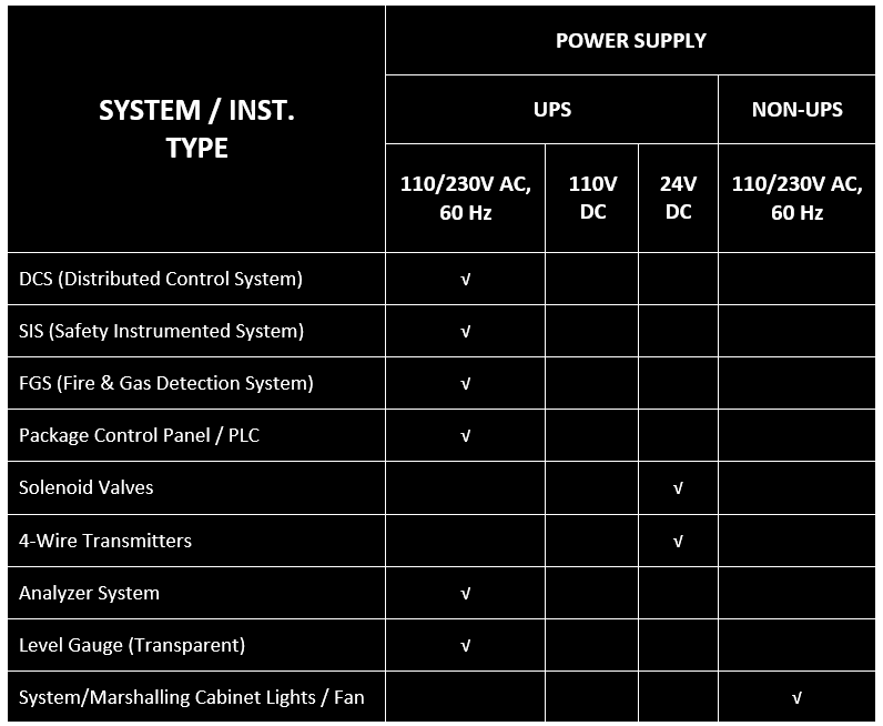
Power Supply & Instrument Air Supply Philosophy
Power Supply Requirements:
Below is a sample illustration to specify the power supply requirement for type of Instruments and control system. Specific requirement if specified in client’s specification/philosophy then same to be covered in I&C design basis.
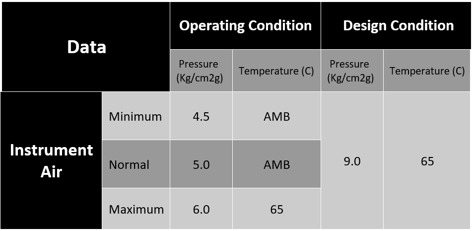
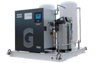
Instrument Air Requirements:
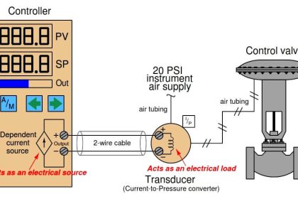
Requirements are generally specified in input document “Process design basis”. Which shall be basis/reference for Instrument manufacturers (e.g. Control & On-off valve), Mechanical package supplier and other pneumatically operated field Instruments.
Generally Instrument dry air of 5.0 kg/cm2(g) is source of pneumatic power to all the pneumatically operated Instruments. However all pneumatic Instruments should be designed to worked at minimum Instrument air pressure as specified in I&C design basis.
Instrument air quality should be in accordance with ANSI/ISA-7.0.01.
Preferred method of Instrument to be specified either “Intrinsic safe (Ex ia)” or “Flameproof (Ex d)” as per the requirements.
Generally 2 wire instruments are Intrinsically safe if required to be used in hazardous area. Preferred method of protection for 4 wire instruments and solenoid valves are generally Flameproof (Ex ”d”).
Basic Requirements Related to Field Instruments and Cables
Field Instruments: I&C design basis covers below listed technical details as minimum,
- Standard for representation of field Instruments and control in P&ID diagram in accordance to ISA S5.1, S5.2 and S5.3.
- Accuracy for all measuring instruments should be specified clearly in design basis with reference to requirement specified in client’s specification. If accuracy requirement are not specified in client’s specification then same to be considered as per standard engineering practices.
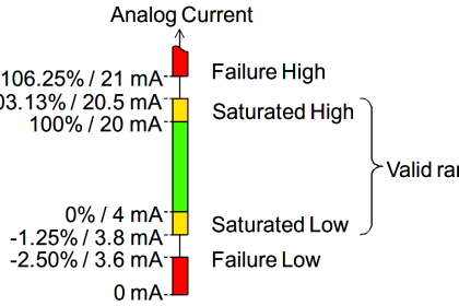
Signal Types
- Analog Signals (4 to 20 mA, HART)
- Digital Signals
- Digital input signals (either pot free or inductive proximity signal)
- Digital output signals (either pot free or Voltage power signal)
- Pot free contact shall always wired through relay
- Frequency Signals (Speed monitoring)
- Serial communication signals
Power supply
- Generally all electronics instruments are 2 wire loop powered, which is powered by connecting control system.
- Except 4 wire instruments and in some cases solenoid valves, transmitters which required separate power supply arrangement.
- Some applications may use 3 wire instruments like HC and H2S gas detectors, etc.
Ingress Protection
- For outdoor application: Instruments, Junction box and local panel generally specified with minimum Ingress protection of IP65 in accordance with IEC 60529 standard.
- For Indoor application: System/Marshalling panels required minimum IP23 in accordance with IEC 60529 standard.
- Wetted part material of field Instrument
- General guideline to use common wetted part material for field instruments is specified in client’s specification/philosophy.
- Generally, minimum SS316 is specified as requirement.
- Special requirement if any should be specified
- NACE (For sour service)
- IBR (For steam application)
Painting & Coating Requirement
- Instruments shall be suitable to use in project environmental condition specified in the project specifications.
- Generally document “Specification for Painting & Coating” reference is mentioned in I&C design basis to cover the requirement. Which is prepared by piping engineering team.
Flange Ratings
- Minimum Flange Rating
- Requirement as specified in client’s specification regarding minimum flange rating for in-line /on-line instruments should cover in the I&C design basis.
- Orifice flange rating shall be minimum 300#. For above 300#, piping material specification should be referred.
- Control valve flange rating shall be minimum 300# for line size up to 6”. Above 6”, piping material specification should be referred.
- Electrical connection type
- Metric Thread (e.g. M20, M25, etc)
- NPT Thread (e.g. ½” NPT, 1” NPT, etc)
Basic Requirements Related to Installation & Related Items
I&C Design basis should clearly specify the technical requirements related to Instrument, Junction box, Local control panel, Cable trays, Instrument cable as per guidelines provided in client’s specification / philosophy.
Type of mounting style of transmitter
- Remote mount
- Direct mount
- Close coupled assembly
- Instrument manifold requirement (2 way, 3 way or 5 way)
- Pneumatic tubing size & Material (Generally stainless steel tube and size of ¼” OD used. ¾” or ½” may use for Pneumatically powered Instruments like, control valve / on-off valve.)
- Cable routing philosophy
- Under ground (duct / tranches)
- Above ground (Perforated trays / Ladder Trays / Cable conduits)
- Process connection for all In-line field instrument generally flanged type as per ANSI B16.5 and B16.47 in accordance with the piping specifications.
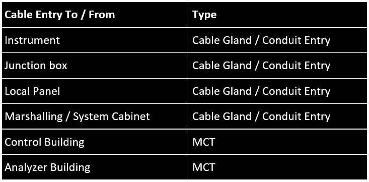
Instrument Cable Entry Type
Instrument cable tray spacing requirement
- Generally 12” Spacing between Instrument signal cable and Power cable should be maintain or as per guidelines specified in client’s specifications.
Spare Philosophy
Spares are to be classified as per their requirement and application as below,
2 Years Operation and Maintenance Spare
- Type and quantity of spare always recommended by supplier.
Startup and Commissioning Spare (As required)
- Required to replace damaged parts/component cause during installation or commissioning phase of project to avoid delay in activity.
- Type and quantity of spare always recommended by supplier.
Consumable Spare (for specified duration, e.g. 6 months or 12 months)
- Type and quantity of spare always recommended by supplier.
Mandatory Spare
- Type and quantity of spare always recommended by supplier as per their past record.
- These type of spares always procure by purchaser.
Recommended Spare
- Type and quantity of spare always recommended by supplier as per their past record.
- These type of spares may or may not procure by purchaser.
Spares related to control system
Installed Spare
- System Cabinet: XX% of electronic modules (signal conditioning modules, signal distribution modules, input / output modules etc.) relays, isolators mounted in each cabinet.
- Marshalling Cabinet: XX% of terminals.
- Multipair Cable: XX% of pairs in each Multipair cable.
- Junction Box: XX% of terminals inside each Junction Box.
Spare Space
E.g. Spare space inside system/marshalling cabinet to install additional hardware in future.
Interest to add any further points? Share with us through below comments section.
Author: Kalpit Patel
Read Next:
- Earthing Scheme in DCS
- PLC Wiring Schemes
- Intrinsic Safety Protection
- What is an Active Barrier?
- NAMUR Output Sensor


Hello inst tools, your team was sharing wonderful technical information for growing engineer’s I’m really thankful to your team
Thank you
Thanks for sharing knowledge.
What is the difference between using 110VAC and 230VAC for DCS panels?
Practically no difference. Only the Power supply module model will differ like 110VAC to 24V DC or 230V AC to 24V DC.
quiet informative