We all know how PLC is important in today’s automation era, so many popular PLC brands are there i.e. Siemens, Yokogawa, AB, ABB, GE, etc. On these PLC controllers, so many LED indications are provided to understand different states of the controller, but to know the status first we need to understand the meaning of those indications.
LED Indications on GE Make PLC
In this article we are going to understand LED indications of one of GE PLCs, specifically for the CPL series, also we will understand the functioning of various ports available on the controller.
In this article, we are going to explain about LED indications of the CPL-410 model of GE make PLC.
About CPL 410 Model
This PAC (Programmable Automation Controller) system which is called RX3iCPL410 is facilitated with an inbuilt Linux server, it supports programming languages like Ladder logic, Structured text, Functional block diagram, and C.
Contains 64Mb of configurable data and program memory, 32K bits for discrete input & output, and 32K words for analog input & output. Bulk memory also supported for data exchange
It supports up to 768 program blocks, one block having 128KB in size, also it supports 4 Nos of independent ethernet LAN (10\100\1000).
Up to 32 Nos Modbus TCP IP clients are permitted, 48 Nos of SRTP (Service Request Transport Protocol) can run simultaneously, and 16 simultaneous Modbus TCP IP server connections.
This PLC can handle operating temperatures up to -40 to 70 Degrees C, it is a DIN rail mount device, supports an 18-30 VDC supply, and does not require a special power supply.
It has been facilitated with five ethernet ports in front and one RJ45 connection on the bottom side, An OLED display is available to navigate and monitor various statuses of the CPU, also many switches with LED indications are available to monitor the status and go through the settings.
We can program and configure the CPU using Proficy Machine Edition software, this system can easily create and redundant system with a 100ms cutover time to the secondary PLC.
Okay, so now we are going to discuss the LED indications for this particular GE PLC model CPL-410.
In the below image we can see a lot of indications and communication ports, in Fig 1 PLC is without any connections and Fig 2 is with running communication channels.
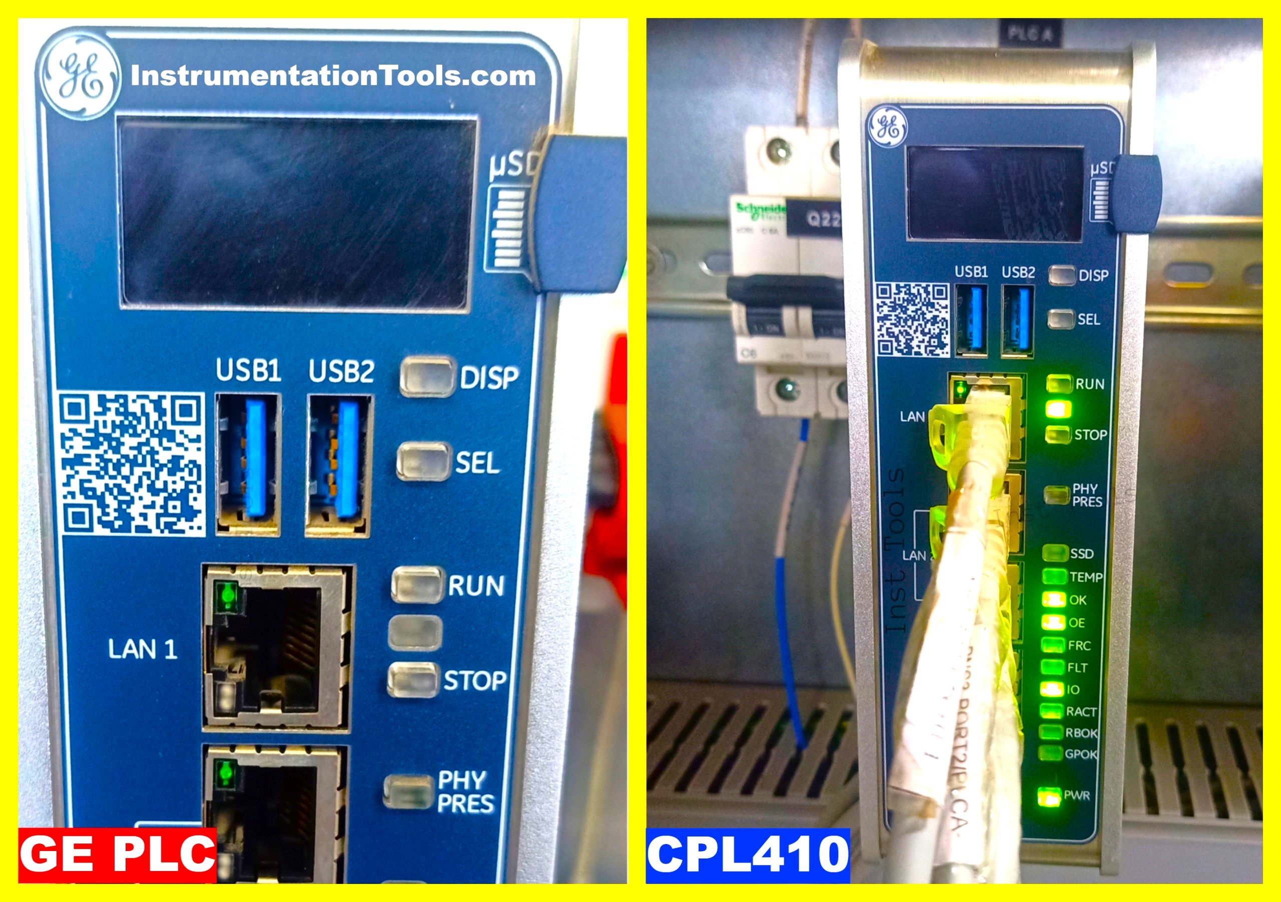
So, Let’s Start from the top-right corner.
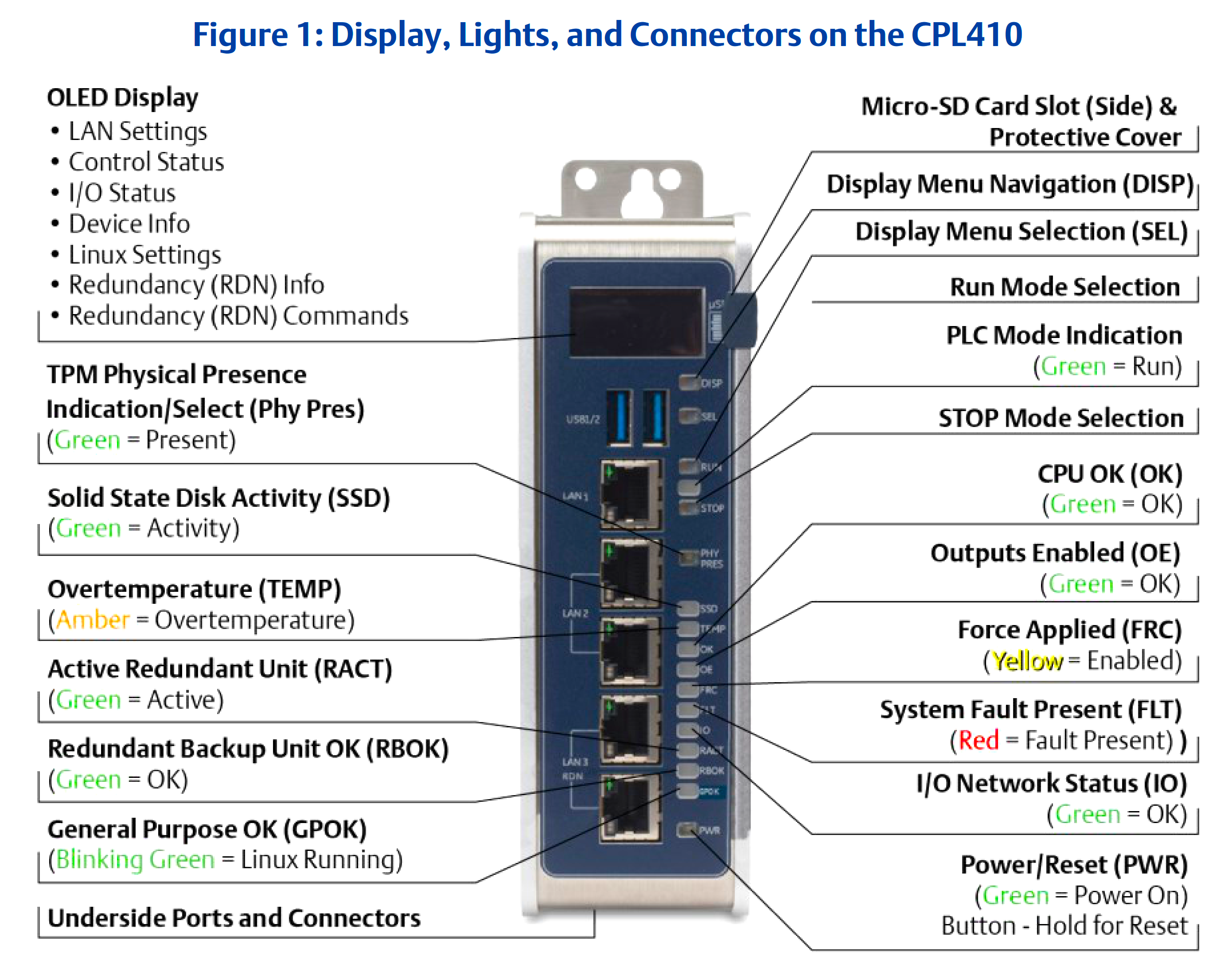
µSD: This slot is to insert a Micro-SD card; the Micro SD Card is used for external storage or load programs; it has a protective cover to prevent damage.
DISP: You can access to Display menu navigation on OLED Display and make changes as per requirement, using this button you can access LAN Settings, Control status, I/O Status, Device information, Linux OS settings, Redundancy information, and Redundancy commands, we can check configured IP of each LAN connection.
SEL: You can guide to selection with this indication cum button for any setting modification where you can navigate your options as per your requirement.
RUN: Being used to run commands to PLC, it activates the OLED menu to select RUN enabled or RUN disabled mode from the PLC, in Run condition green indication will blow just below to run button.
STOP: It is being used to send a Stop command to PLC, you can select Stop Enabled or Stop Disabled by using this button for PLC.
PHY PRES: TPM (Trusted Platform Module) Physical Presence indication cum selection, this will blow the green light in healthy condition.
SSD: Solid State Disk Activity, Green indication in healthy condition. This is for checking the healthiness of Solid State Disk or drive where data is being stored.
TEMP: This indicates that the controller met with overtemperature, it will indicate an amber LED indication when the temperature goes beyond the limit.
OK: This signal indicates that the CPU is OK and in Healthy condition.
OE: Output enabled, green indication when it is OK.
FRC: When we apply force to any module or equipment, a yellow indication will glow which shows that the Force signal is enabled.
FLT: This indication will glow with a red light when a System Fault is present, A system fault happens in case of an issue with any module.
IO: This LED indicates the healthiness of IO network status; green indication will glow in healthy condition.
RACT: A redundant system is a must to avoid process failure in case of any issue with the primary controlling system, also close monitoring is required on the redundant system to ensure availability all the time, RACT LED indication will indicate that Redundancy active or Active redundant unit, indication will be green when redundant devices are active, this LED will be getting activated once Hot Stand by Redundant CPU is ready.
RBOK: This indicates that the Redundant Backup Unit is OK, the indication will be green.
GPOK: After Linux booted successfully and restarted the CPU, This LED indication will blink green and indicate that the General purpose is OK, i.e., an Operating system in healthy condition or ready for user logins or we can say that Linux is running.
PWR: Power is ON, also we can reset the controller with this button, we have to hold the PWR button to reset the PLC, in healthy condition it will glow green.
Communication Ports in PLC
Let’s have some understanding about communication ports:
USB1: This port is assigned to Linux and it can be used to have access to keyboards, Memory sticks, Pen drives, and other memory devices with properly installed drivers.
USB2: This port is assigned to the controller runtime PACS (Programmable Automation Controller)
LAN: LAN ports are being used to configure plant communication packages and Hot Standby redundancy where two LAN3 group ports are being used to fulfill this purpose. they provide a high-speed data synchronization link between the two CPUs. Connect the upper LAN3 port of the Primary CPU to the upper LAN3 port of the Secondary CPU and connect the lower LAN3 port of the Primary to the lower LAN3 port of the Secondary.
Front panel LAN:
-LAN-1: This port is un-switchable and connects to the uppermost RJ45 connector.
-LAN-2: Connects in middle two RJ45 connectors and it can switch internally.
-LAN-3: Will connect in lower two RJ45 connectors, these ports are also able to switch internally, this port is being used to provide hot standby redundancy to the system.
Underside LAN:
-RJ45: This port supports Serial IO protocol, also this port is assigned to the Linux system itself.
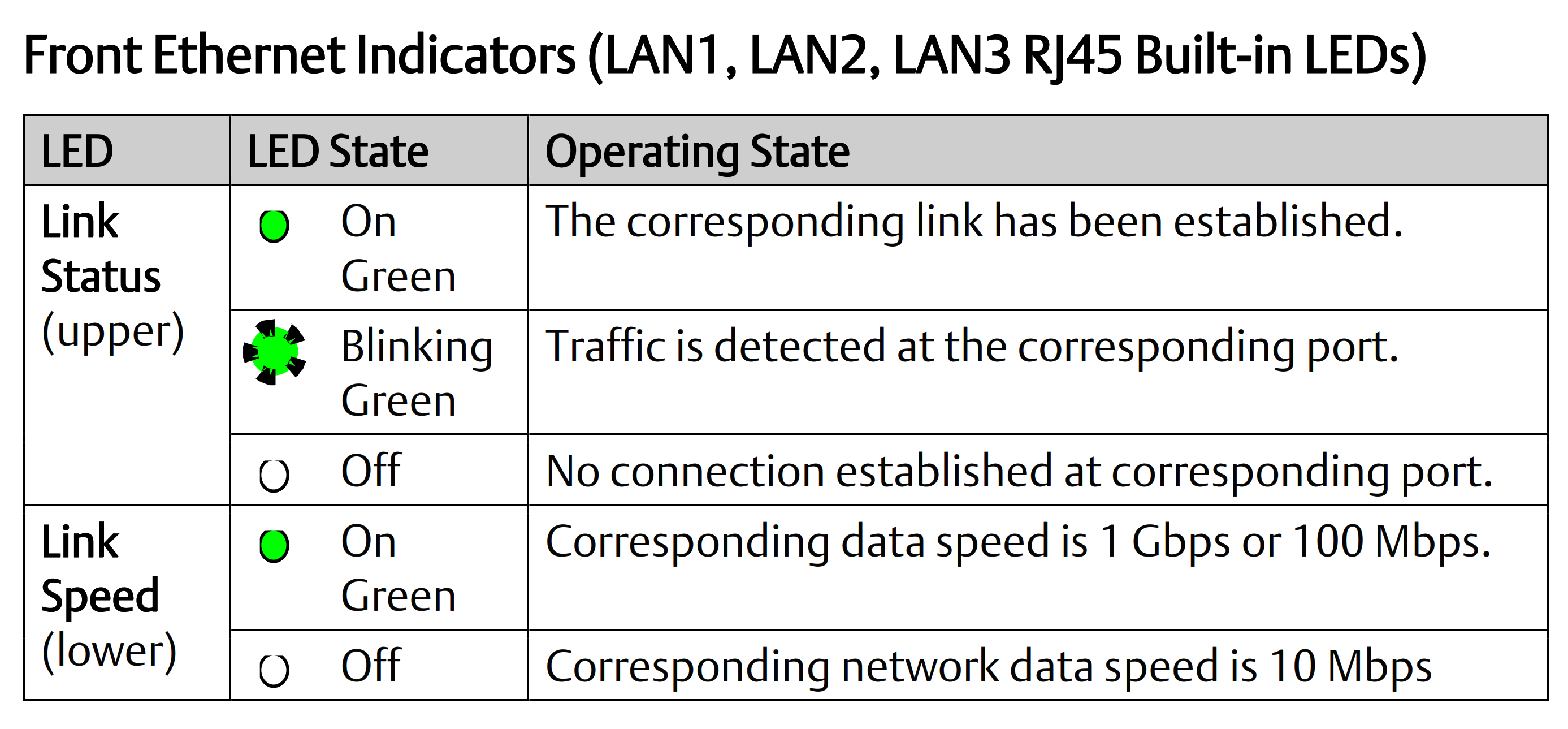
LAN Port’s speed and healthiness of link is very crucial for proper communication, let’s have a look at the upper and lower indications of LAN port and the meaning of that indication.
LAN Ports-Status (upper indication): Green indication: The corresponding link has been established, Blinking green: Traffic detected, Off, No connection.
LAN Ports-Speed (lower indication): Green On: Data speed is 1 Gbps or 100 Mbps, Off: Network data speed is 10 Mbps
See the below figure to understand indications for LAN ports.
Other Ports Available on the Bottom Side of PLC
RJ45: This is a serial COM port, where we can connect a communication channel with an RJ45 connector, we can use this port for direct ethernet connection, or we can communicate Modbus or serial communication channel using a TCP IP converter (Serial to Ethernet). Kindly note that the RJ connector comes with 8 pins and connect with wires which are combined in twisted pair, this twisted pair help to decrease cross talk and cancel electromagnetic interference.
Below ports are available on the bottom side of PLC (Fig.4)
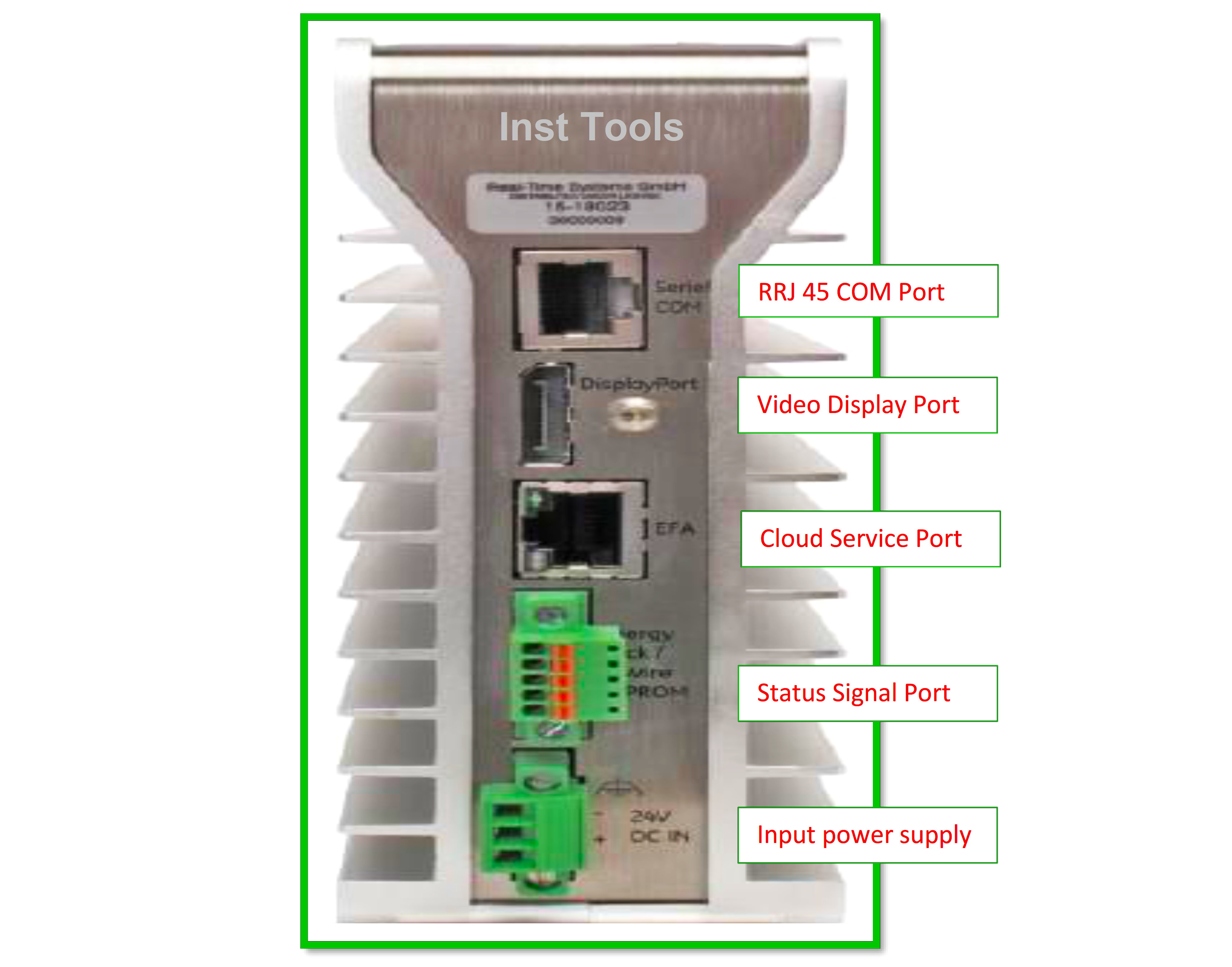
Display Port: It’s a Video Display Port, we can use this port to transmit video and audio simultaneously, or separately. DP can transmit signal in rage to 144Hz to 4k.
EFA: This is an IICS (Informatica Intelligent Cloud Services) Cloud port, this is could cloud-based service for integration and data management, using this platform you can configure connections, create users, run, schedule, and monitor activities or tasks.
EPCSS: Energy Pack Control & Status Signal, it’s a terminal block with 5 Nos of wiring terminals. Although EPCSS is optional to use when it is used, it allows the PLC Controller to save its current state upon loss of power.
24DC IN: Three-wire terminal block for 24V DC power supply to PLC.
Let’s have a look at the summary of all LED indications in Fig. 5
So, this was a basic understanding of LED indications and various ports of GE make PLC.
If you liked this article, then please subscribe to our YouTube Channel for Instrumentation, Electrical, PLC, and SCADA video tutorials.
You can also follow us on Facebook and Twitter to receive daily updates.
Read Next:
- PLC Hardwired I/O and Serial I/O
- S7-1500 S7-1200 S7-400 S7-300
- HMI Screen Design Applications
- Fault Diagnosis PLC Documents
- Implement UDT in PLC Programming