Inst ToolsInst ToolsInst Tools
  • Courses
  • Automation
    • PLC
    • Control System
    • Safety System
    • Communication
    • Fire & Gas System
  • Instrumentation
    • Design
    • Pressure
    • Temperature
    • Flow
    • Level
    • Vibration
    • Analyzer
    • Control Valve
    • Switch
    • Calibration
    • Erection & Commissioning
  • Interview
    • Instrumentation
    • Electrical
    • Electronics
    • Practical
  • Q&A
    • Instrumentation
    • Control System
    • Electrical
    • Electronics
    • Analog Electronics
    • Digital Electronics
    • Power Electronics
    • Microprocessor
  • Request
Search
  • Books
  • Software
  • Projects
  • Process
  • Tools
  • Basics
  • Formula
  • Power Plant
  • Root Cause Analysis
  • Electrical Basics
  • Animation
  • Standards
  • 4-20 mA Course
  • Siemens PLC Course
Reading: Grounding or Earthing Scheme in DCS or PLC Systems
Share
Font ResizerAa
Inst ToolsInst Tools
Font ResizerAa
  • Courses
  • Design
  • PLC
  • Interview
  • Control System
Search
  • Courses
  • Automation
    • PLC
    • Control System
    • Safety System
    • Communication
    • Fire & Gas System
  • Instrumentation
    • Design
    • Pressure
    • Temperature
    • Flow
    • Level
    • Vibration
    • Analyzer
    • Control Valve
    • Switch
    • Calibration
    • Erection & Commissioning
  • Interview
    • Instrumentation
    • Electrical
    • Electronics
    • Practical
  • Q&A
    • Instrumentation
    • Control System
    • Electrical
    • Electronics
    • Analog Electronics
    • Digital Electronics
    • Power Electronics
    • Microprocessor
  • Request
Follow US
All rights reserved. Reproduction in whole or in part without written permission is prohibited.
Inst Tools > Blog > Control Systems > Grounding or Earthing Scheme in DCS or PLC Systems

Grounding or Earthing Scheme in DCS or PLC Systems

Last updated: September 28, 2022 2:40 pm
R Jagan Mohan Rao
Control Systems PLC Tutorials
2 Comments
Share
4 Min Read
SHARE

First, let us understand the difference between grounding and earthing.

Contents
Grounding or Earthing SchemeTypesIsolated local Ground (G1)Isolated Common Ground Reference (G2)Control System Ground (G3)Dedicated Plant Earth Ground (G4)

Whenever the DCS or PLC systems are grounded, they still not connected to the earth. The system has a ground bus bar inside located at an appropriate place to which all internal grounding connection is returned. Once the final ground bus bar is connected to an actual-earth pit or earth grid that the system finally earthed.

Improper earthing or grounding of Distributed Control System (DCS) or Programmable Logic Controller (PLC) may result in either mal-operation of the control system or a controller or failure of electronic cards or sometimes even embedded software gets erased.

In the case of DCS or PLC each cubicle is having a ground bus bar to which the controller chassis, shields can be connected. These bus bars are then returned to a final ground bus bar from where the connection is then taken to earth pit or earth grid.

The earth pit must have a small earth resistance ( much less than 1 ohm). usually, the earth resistance can be measured by a three probe method.

Grounding or Earthing Scheme

Grounding or Earthing Scheme in DCS or PLC Systems

Types

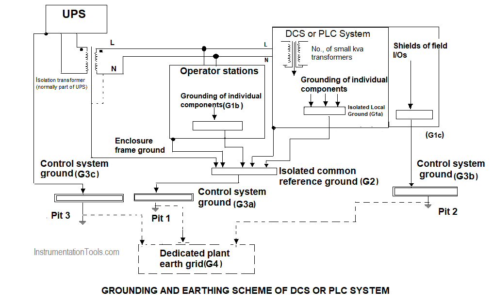
There are four layers required for the correct and effective grounding and earthing.

  1. Isolated local Ground (G1)
  2. Isolated Common Ground Reference (G2)
  3. Control System Ground (G3)
  4. Dedicated plant earth Grid (G4)

Isolated local Ground (G1)

Isolated local Ground (G1) is where power supplies, internal power component enclosures, etc., are grounded on a bus bar. This refers typically to one control system.

Isolated Common Ground Reference (G2)

Isolated local Ground (G1) connection from each of the control systems, there within the realm is terminated along with the frame or cabinet or overall enclosures are individually terminated for grounding to create an Isolated Common Ground Reference(G2).

It should be noted that the enclosure earthing minimized the results of Electromagnetic interference.

Control System Ground (G3)

It is where the incoming power supply isolation transformer secondary is grounded along with ground connection obtained from Isolation common ground reference(G2). This control system ground is considered as the final earth pit for that location. It can be terminated on the dedicated plant earth Grid (G4).

The control system ground (G3) or the final earth pit connected to the local control systems should be separate earth pit. Which then can be connected to a dedicated plant earth system. This control system G3 should not be shared with other plant systems.

Dedicated Plant Earth Ground (G4)

The Dedicated plant earth ground (G4) may or may not exist. If exists it is supposed to have the lowest impedance. It consists of many earth pits in a grid fashion.

The cable used for grounding should be in green with yellow marks.

The ground bus bars to be used should be copper bus bars with approximately 10 mm as the thickness and 50 mm in width.

Reference: David Brown, David Harrold, and Roger Hope,” Control Engineering: Control system power and grounding better practice,”

Interest to add any further points? Share with us through below comments section.

If you liked this article, then please subscribe to our YouTube Channel for PLC and SCADA video tutorials.

You can also follow us on Facebook and Twitter to receive daily updates.

Read Next:

  • Types of PLC wiring Diagrams
  • DCS Program Furnace Draft
  • Project Planning of PLC System
  • Different Parts of DCS
  • What is a Control Panel?
Don't Miss Our Updates
Be the first to get exclusive content straight to your email.
We promise not to spam you. You can unsubscribe at any time.
Invalid email address
You've successfully subscribed !

Continue Reading

Typical HMI Screen Design for Water Treatment Plant
PLC Timer Instructions
Dosing Pump PLC Logic
Remote Factory Acceptance Test
Basic Concepts of the Safety Relay
Top 100 PLC Projects List
Share This Article
Facebook Whatsapp Whatsapp LinkedIn Copy Link
Share
2 Comments
  • Essam says:
    March 23, 2020 at 12:39 am

    What is the effect of welding works on instrumentation??

    Reply
  • mahmood roostaei says:
    May 23, 2023 at 5:00 pm

    Shall all three pits pit1 to pit3 have less than 1 ohm resistance separately?
    or 1 ohm can be achieved by considering all the pits and the dedicated plant earth grid G4 resistance totally?

    Reply

Leave a Reply Cancel reply

Your email address will not be published. Required fields are marked *

Stay Connected

128.3kFollowersLike
69.1kFollowersFollow
210kSubscribersSubscribe
38kFollowersFollow

Categories

Explore More

PLC Motor Operation based on Time Cycle Sequence – Program
Fundamental Motion Control Commands
How to Do Logic Checks During Plant Pre-Commissioning
Steps to Configure TCP/IP Communication in Siemens S7-1200 PLC
PLC Data Comparison Instructions
Flexible Input Output Modules
How to Troubleshoot a PLC System?
Animation of Electromagnetic Relay

Keep Learning

Introduction to SCADA

Boolean Logic to PLC Programming

Boolean Logic to PLC Programming

Alarm prioritization

What is Alarm Prioritization? – Types of Alarms

PLC Ladder Logic for Demultiplexer

1 to 8 Demultiplexer PLC ladder diagram

PLC Sequential Lights Control Example

PLC Timer Example: Sequential Control of Three Lights with Reset

Basics of Anti-Surge Control System

What is Anti Surge System?

plc-analog-signals-wiring-techniques

PLC Analog Signals Wiring Techniques

Site Acceptance Test (SAT) of PLC System

PLC System Site Acceptance Test (SAT)

Learn More

Open-Tank-DP-Level-Transmitter-with-Zero-Suppression-Calibration

DP Level Transmitter with Zero Suppression Calibration

Power Electronics Objective Questions

Power Electronics Objective Questions

What is a Magnetic Contactor

What is a Magnetic Contactor? – Principle, Types, Advantages

Single Phase Half-controlled Rectifier RL Load With FD

Phase-Controlled Half-Wave Rectifier With Freewheeling Diode

What is a Fuse

What is a Fuse ?

RTD

Why 4 wire RTD Measurement Accuracy is better than 2 and 3 wire RTD?

Mathematical Models of Physical Systems

Differential Equations of Physical Systems & Dynamics of Robotic Mechanisms

safety control system

Safety Instrumented Burner Management System

Menu

  • About
  • Privacy Policy
  • Copyright

Quick Links

  • Learn PLC
  • Helping Hand
  • Part Time Job

YouTube Subscribe

Follow US
All rights reserved. Reproduction in whole or in part without written permission is prohibited.
Welcome Back!

Sign in to your account

Username or Email Address
Password

Lost your password?