Inst ToolsInst ToolsInst Tools
  • Courses
  • Automation
    • PLC
    • Control System
    • Safety System
    • Communication
    • Fire & Gas System
  • Instrumentation
    • Design
    • Pressure
    • Temperature
    • Flow
    • Level
    • Vibration
    • Analyzer
    • Control Valve
    • Switch
    • Calibration
    • Erection & Commissioning
  • Interview
    • Instrumentation
    • Electrical
    • Electronics
    • Practical
  • Q&A
    • Instrumentation
    • Control System
    • Electrical
    • Electronics
    • Analog Electronics
    • Digital Electronics
    • Power Electronics
    • Microprocessor
  • Request
Search
  • Books
  • Software
  • Projects
  • Process
  • Tools
  • Basics
  • Formula
  • Power Plant
  • Root Cause Analysis
  • Electrical Basics
  • Animation
  • Standards
  • 4-20 mA Course
  • Siemens PLC Course
Reading: How to Use ModScan Software for Testing Modbus Communication?
Share
Font ResizerAa
Inst ToolsInst Tools
Font ResizerAa
  • Courses
  • Design
  • PLC
  • Interview
  • Control System
Search
  • Courses
  • Automation
    • PLC
    • Control System
    • Safety System
    • Communication
    • Fire & Gas System
  • Instrumentation
    • Design
    • Pressure
    • Temperature
    • Flow
    • Level
    • Vibration
    • Analyzer
    • Control Valve
    • Switch
    • Calibration
    • Erection & Commissioning
  • Interview
    • Instrumentation
    • Electrical
    • Electronics
    • Practical
  • Q&A
    • Instrumentation
    • Control System
    • Electrical
    • Electronics
    • Analog Electronics
    • Digital Electronics
    • Power Electronics
    • Microprocessor
  • Request
Follow US
All rights reserved. Reproduction in whole or in part without written permission is prohibited.
Inst Tools > Blog > PLC Tutorials > How to Use ModScan Software for Testing Modbus Communication?

How to Use ModScan Software for Testing Modbus Communication?

In this post, we will see how to use Modscan software for testing Modbus communication in industrial applications.

Last updated: September 4, 2023 12:10 pm
Viral Nagda
PLC Tutorials
No Comments
Share
5 Min Read
SHARE

Modbus communication is a widely used communication protocol in industrial automation. It is basically divided into three types – Modbus TCPIP, Modbus RTU, and Modbus ASCII. Modbus TCPIP uses Ethernet communication, whereas Modbus RTU and Modbus ASCII use serial line communication.

Apart from PLC, these protocols are also available in many devices like fire alarm annunciators, variable frequency drives, PID controllers, etc. This means, many devices nowadays provide these protocols so that users can get maximum data from them as much as possible.

So, PLC programmers need to know that there are many software available to test the protocol in these devices. One of the most common and simple used software is Modscan. In this post, we will see how to use Modscan software for checking Modbus communication.

ModScan Software

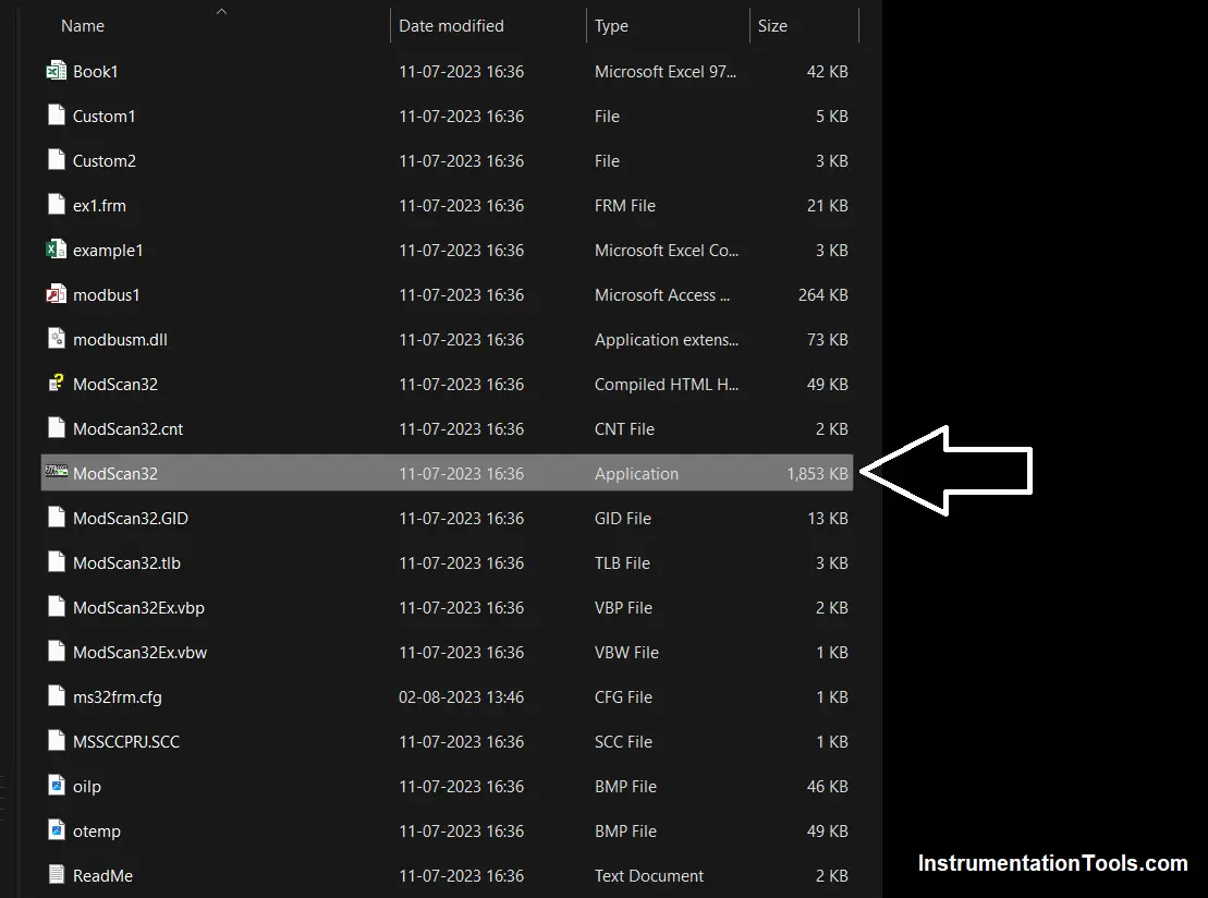
When you download the setup file of Modscan on your PC, you will see the following files below. As per the image, double-click the application file. Directly, the software will run through this, without a need for installation.

Download Modscan Software: Click Here

ModScan Software

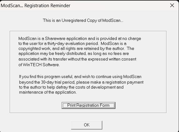
As soon as you run this application, you will get four popups asking the user to register. This is shown in the figure below.

Modscan32

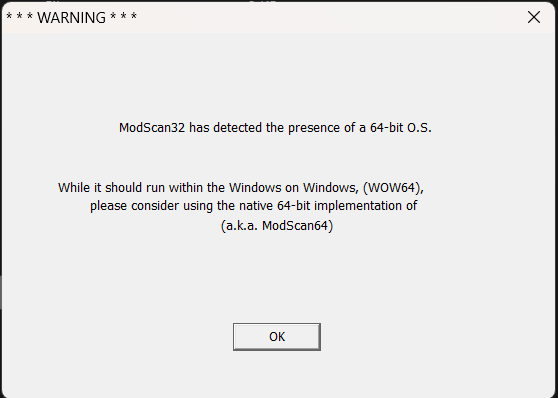
You just need to press the Esc button every time a popup appears. It means you can run the software for a demo time of mostly 5 minutes.

Modscan Software Registration

Then, the software will expire and you will have to close the software window and again follow this process to start running it once again.

Modscan Software Link
WinTECH Software Site

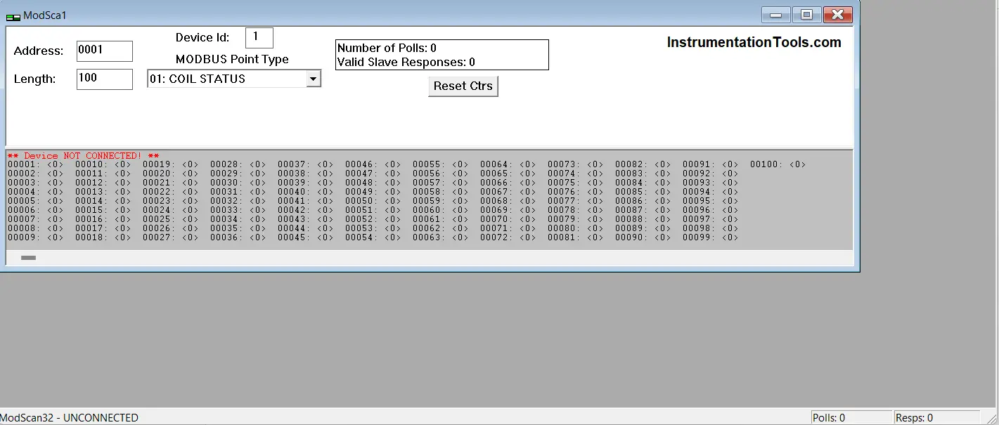
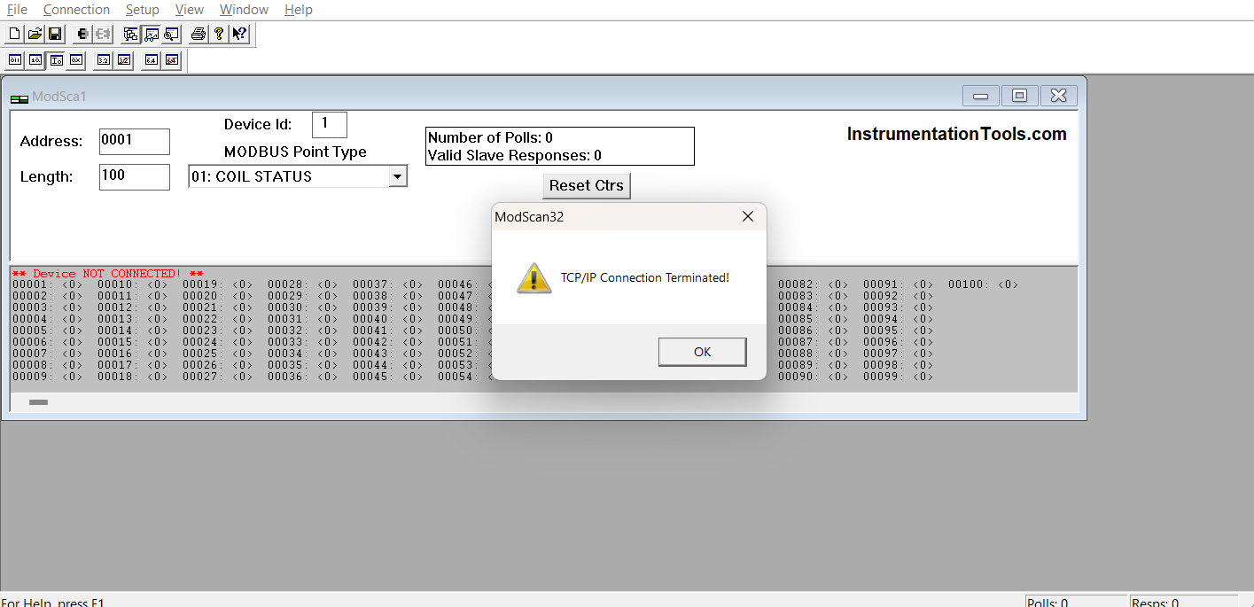
Once you have closed all four of these windows, you will get the following window as shown below. This is the main running window.

Here, you have to choose all the parameters required to establish successful Modbus communication with the device connected.

Enter the following details first – register address, length, device ID, and register type (function code).

How to Use ModScan Software for Testing Modbus Communication

Once you have entered all these parameters, the next step is to connect the device. Click connect in the connection tab of the toolbar, and you will get the following popup as shown below.

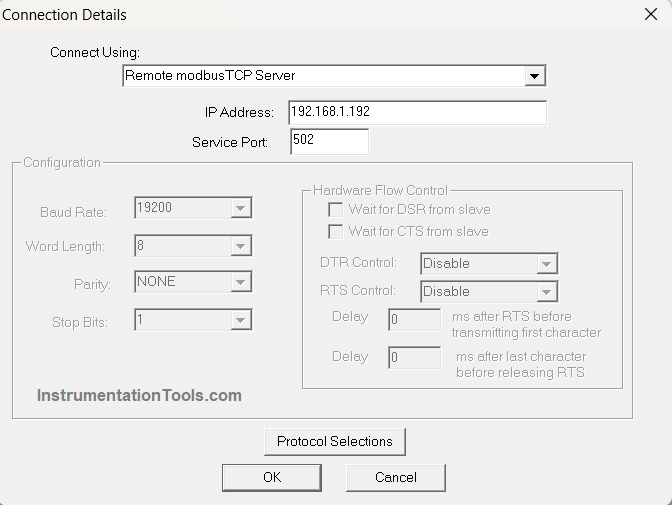
This setting allows you to connect to the device by choosing any three protocols – TPCIP, RTU, and ASCII. If you are connecting to a Modbus TCPIP device, then just select Remote Modbus TCP server as shown below and enter the IP address of the device in the next tab (shown below as 192.168.1.192).

Keep the service port as 502 and just hit the OK button.

Remote Modbus TCP Server

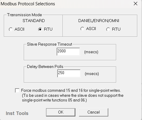
If you are connecting to Modbus RTU or ASCII device, then first click protocol selections as shown below and you will get the following popup.

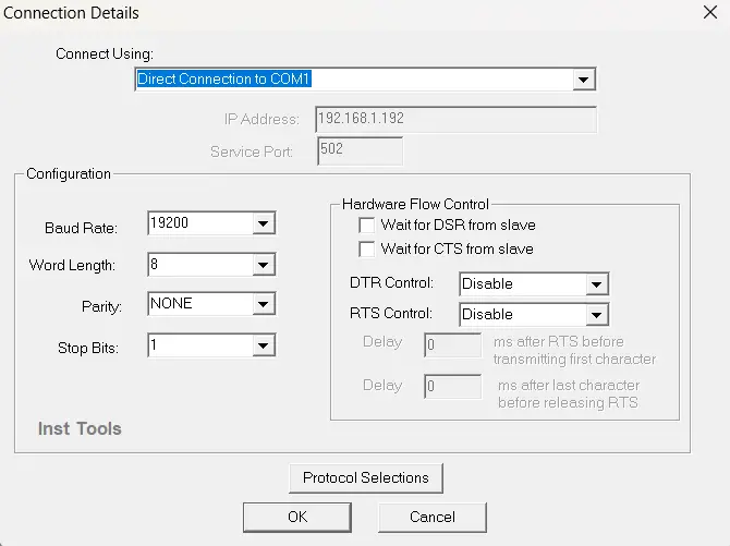
Before that, change the connect using the tab to the COM port of your PC.

Modbus Protocol Selection

For example, if you have connected your USB to a serial converter in COM1 of your PC, then select the option as shown below and enter details like baud rate, data length, parity, and stop bit.

Modscan Configuration Parameters

After clicking OK, if the device has established communication with the PC, then it will show the values, else it will give errors depicting what is the issue.

Testing Modbus Communication

You can change the display format option as shown below, for viewing the data in the required format.

Download Modscan software

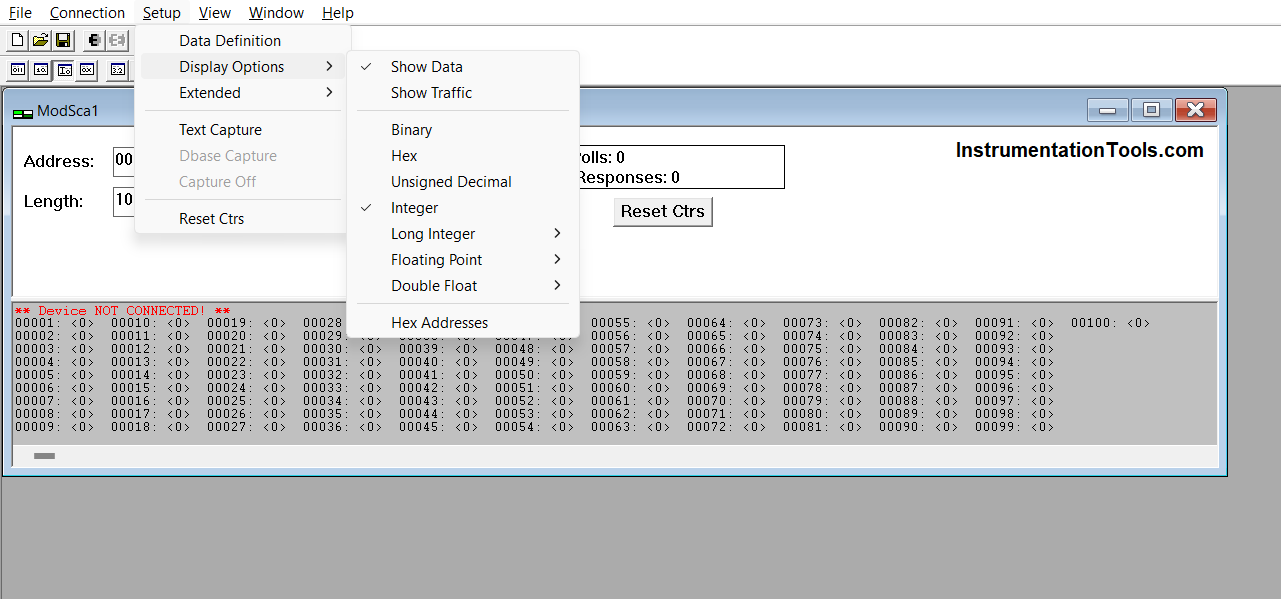
In this way, we saw how to use Modscan software on a PC to check Modbus communication with the device.

If you liked this article, then please subscribe to our YouTube Channel for Instrumentation, Electrical, PLC, and SCADA video tutorials.

You can also follow us on Facebook and Twitter to receive daily updates.

Read Next:

  • MOVE Instruction in PLC
  • Allen Bradley PLC Hardware
  • Motor Classic Control Circuits
  • Control System Cyber Security
  • How to Design an Effective HMI?
Don't Miss Our Updates
Be the first to get exclusive content straight to your email.
We promise not to spam you. You can unsubscribe at any time.
Invalid email address
You've successfully subscribed !

Continue Reading

PLC Code to Start & Stop Motor and Pump as per Logic
How to Start Writing SCL Language in Siemens Tia Portal?
Various Causes for PLC Going in Stop Mode
1 to 8 Demultiplexer PLC ladder diagram
What is CODESYS? Why Do You Need to Learn it?
Automatic Car Washing using PLC
Share This Article
Facebook Whatsapp Whatsapp LinkedIn Copy Link
Share
Leave a Comment

Leave a Reply Cancel reply

Your email address will not be published. Required fields are marked *

Stay Connected

128.3kFollowersLike
69.1kFollowersFollow
210kSubscribersSubscribe
38kFollowersFollow

Categories

Explore More

How to Backup and Restore from Simatic Prosave HMI?
How to Troubleshoot a PLC System?
Automatic Packing of Bottles Programming
Applications of PLC Programming in Bottle Filling Process
Scaling with Parameters (SCP) Instruction in PLC
SCADA Systems
Types of Expressions in the SCL Language of the Tia Portal
How to Connect a Solenoid Valve with PLC?

Keep Learning

PLC Timer Application in Security Camera Recording

PLC Timer Application in Security Camera Recording

PLC Programmer Unknown Do's

Unknown Do’s Need to Know as a PLC Programmer

Online and Diagnostics of Siemens PLC

How to Use Diagnostic Buffer for SIEMENS PLC?

How to Download Rslogix Free

Download Allen Bradley RSLogix PLC Software

PLC Karnaugh maps

How to Simplify PLC Coding Using Karnaugh Maps?

Overview of Industrial Control Systems

Overview of Industrial Control Systems

Function Module in Siemens PLC

What is Function Module in Siemens PLC?

PLC Program for Traffic Light Sequence using Functional Blocks

PLC Program for Traffic Light Sequence using Functional Blocks

Learn More

Pre-commissioning or Commissioning Activities

Pre-commissioning or Commissioning Activities

Digital Instrument Example

Digital Measuring Instruments – Types, Functions, Advantages, Disadvantages

Electrical Machines Objective Questions

Electrical Machines MCQ Series 1

Difference between Calibration and Ranging

Difference between Calibration and Ranging

Thermocouple Reference Junction

Thermocouple Working Principle

Modbus scan

How Modbus Communication works

Spring Loaded Variable Area Flowmeter Working Principle

Spring Loaded Variable Area Flow Meter Working Principle

PRV

Direct-actuated Safety and Relief Valves

Menu

  • About
  • Privacy Policy
  • Copyright

Quick Links

  • Learn PLC
  • Helping Hand
  • Part Time Job

YouTube Subscribe

Follow US
All rights reserved. Reproduction in whole or in part without written permission is prohibited.
Welcome Back!

Sign in to your account

Username or Email Address
Password

Lost your password?