After we have discussed the meaning and importance of redundancy in Automation systems, today we are going to have an overview of SIEMENS redundant solutions.
SIEMENS is one of the most important leading companies in the Automation field, it is known for its flexible software (TIA portal) and its reliable Hardware components (PLCs – Circuit Breakers – HMI – …).
Redundant programmable logic controllers from Siemens have proved themselves in operation and thousands are in service.
Difference Between Hardware & Software Redundancy
First of all, and before we get into SIEMENS redundancy solutions, we had to differentiate between these two types of redundancy:
Hardware Redundancy in PLC
Hardware Redundancy is a PLC model that you can see in (S7-400H & S7-1500H), it is used in critical processes such as power plants, gas production plants, and high-speed rotary machinery.
In case of master CPU failure, the standby CPU can take control in 10ms order with previous updates from the process. (In this manner, the changeover is bumpless).
Software Redundancy in PLC
Software Redundancy can use any type of S7-300 and S7-400 standard CPUs, the redundant link between the CPUs can be implemented in standard communication links over MPI, Profibus-DP, or Industrial Ethernet, and the switchover time (when a fault on the primary CPU will cause the standby CPU to take over the process) is measured in seconds.
In general terms, this can be described as a warm-backup system: relatively cheap, most of the programming for the redundancy must be done by yourself, and redundant IOs are limited.
So, as we can notice the main advantage of hardware redundancy over software redundancy is the “response rate”, Hardware systems have a faster response/switchover time.
Requirements for Software Redundancy
Hardware Requirements
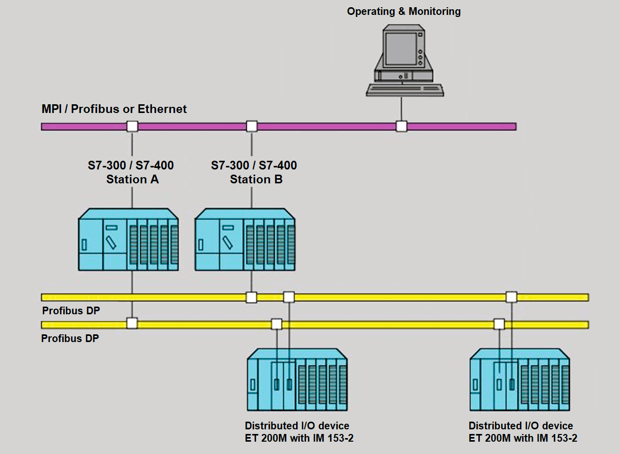
Two S7-300 and/or S7-400 stations each one equipped with a CPU and a connection for a DP master system. The two stations are linked by means of a bus system that you can use to exchange data.
ET 200M distributed I/O devices with redundant DP slave interface module IM 153-2 are connected to DP master systems.
The DP slave interface module allows the failover from the first to the second interface in the event of a fault in order to forward process status data from the second DP master to the I/O.
Software requirements
We need to install the STEP 7 Basic Package V5.2 or higher to assign parameters to the blocks for software redundancy.
“Software Redundancy” How Does It Work?
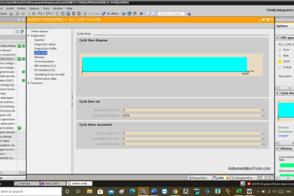
Before understanding the software redundancy algorithm, you have to learn further detail about the PLC scan cycle and how does a normal PLC work?
This article (scan cycle article) would help you to understand How a PLC executes a normal scan cycle.
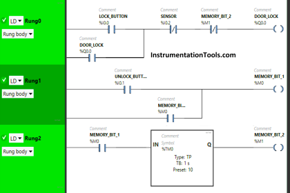
Step 1: The Redundant Software
First of all, you have to download the fault-tolerant component of the software on both PLCs (the master and the standby stations).
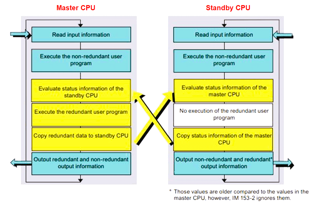
While the master CPU is processing the redundant user program, it is skipped in the standby CPU.
As the standby CPU skips this component of the program that would help to prevent inconsistency of the two program components, e.g. as a result of alarms, different cycle times, etc.
This means that the program on the standby station is always ready to take over-processing.
Step 2: The master station continuously transfers updated data to the standby station
To avoid having to start the redundant user program “from scratch” after the failure of the master station, the master station continuously transfers its actual process data to the standby station.
A master to standby station changeover is initiated immediately after a fault has been detected at a CPU, at a DP master, or at a DP slave within the master station. With this type of changeover, the standby station takes over the process and assumes the master function.
Step 3: Areas of the redundant software component
The redundant software component contains a process image, an IEC timer area, an IEC counter area, a bit memory address area, and a data block area.
Only the redundant software is allowed write access to those areas.
Those contiguous areas are scanned during the assignment of parameters for the “SWR_START” startup block (OB100).
Step 4: Processing unilateral I/O devices
The term unilateral I/O devices denote I/O modules that are not addressed in the redundant component of the user program, i.e. they are only assigned to one CPU.
In addition to the redundant software component, it is, of course, also possible to load a program that controls the unilateral I/O devices of the relevant CPU.
Software redundancy does not have any influence on that component of the program.
Step 5: Data exchange between the two stations
The non-redundant component of the program can exchange its data with the redundant software by means of suitable data blocks.
Those data blocks are exchanged by means of the software redundancy system and are therefore made available to the partner station.
The inputs are written to the process image of inputs (PII) at the start of OB 1.
The redundant software is processed before any data of the redundant software component (PIO, bit memories, DBs, timers/counters, and instance DBs) is transferred to the standby system.
The standby station must receive the data from the active station after having completed its startup, or after redundancy has been recovered in that software component.
At the end of OB 1, the data of the redundant PIO is written to the process image of outputs at the master and standby stations and is transferred from there to the I/O devices at the end of the OB cycle.
NOTE:
Interrupts can be received by the active station at any time and are processed immediately.
Interrupts can be lost if a changeover takes place at that moment or shortly afterward.
Step 6: Master to standby changeover
In order to avoid having to start the standby station “from scratch” after master failure, a complete and consistent PIO of the fault-tolerant program component is transferred to the standby station to cover emergency/changeover situations.
The time required for the transfer may take longer than one cycle, depending on the communication mode and the volume of data to be transferred.
The DP slave stations failover automatically, for example after detection of a problem on the DP master or on the DP bus of the DP master station.
During this DP slave changeover, the most recently output PIO values are frozen on the DP slaves.
Step 7: Recovering software redundancy after repairs
To recover software redundancy, for example after the failure of a CPU, all configuration data and the entire program must be loaded from the programming device or memory card to the replacement CPU. That CPU is then started.
Resources
- SIMATIC S7-300/S7-400 Software redundancy for SIMATIC S7.
If you liked this article, then please subscribe to our YouTube Channel for Instrumentation, Electrical, PLC, and SCADA video tutorials.
You can also follow us on Facebook and Twitter to receive daily updates.
Read Next: