We explained the different factors of fuse to choose the right type for a electronics or electrical panel with our step-by-step guide.
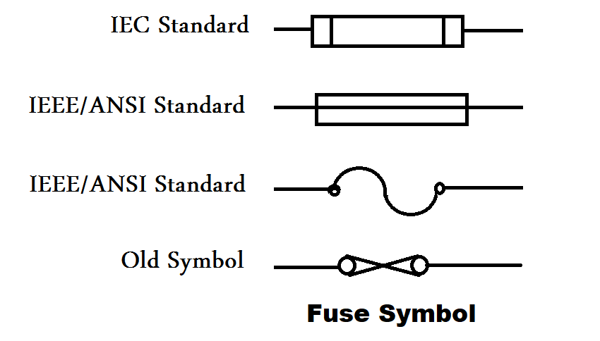
Fuse
The main purposes of fuse serve
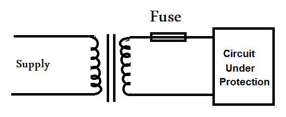
1. To protect electrical, electronic components and equipment from costly damage caused by overcurrents.
2. To isolate subsystems from the main system once a fault has occurred.
3. A fuse is equivalent to switch run but operated automatically.
4. Fuse is the device that provides safety for human beings and is consisting of a small piece of wire that melts and breaks an electric/electronic circuit if the current exceeds the safe value.
In some instances, we are required to protect only the wiring and prevent a fire. In other instances, we may be protecting very sensitive electronics equipment.
Factors
Important factors to be considered while selecting a fuse include
- physical size,
- amperage,
- voltage,
- type,
- ambient temperature, and also
- special characteristics.
Alo Read: Important Factors of Fuse
A number of important rules for proper fusing are also included.
Formula
Selection of a fuse depends on the below formula
Current rating of a fuse = Power (Watts) / Voltage (Volts) X Fusing factor
Fusing factor ranges from 1.2 to 2.
The value of the fusing factor is must be greater than 1. If it is 1.2 then it means that the operating current is 20% more than the rated current.
Characteristics of a Fuse
There are different types of Fuses are available in the market for industrial applications. The fuses are often categorized by the following characteristics.
- Current Rating
- Voltage Rating
- Melting Time
- Interrupting Rating or Breaking capacity
- I2T Value of the Fuse
- Packaging
- Temperature
The first two i.e. Current Rating, Melting Time of the Fuse are generally related to the Thermal Characteristics of the fuse. On the other hand, the Voltage and Interrupting Rating are classified under Interrupting Characteristics of the fuse.
As the amount of current in the circuit starts increases, the melting time of the conducting element in the fuse start decreases. This is because the power dissipation (determined by I2R) will increase and the temperature of the element increases rapidly.
If there are any inductive components within the circuits, then the melting of the conductive element in the fuse is not enough for interrupting the current. In spite of the element in the fuse melts, there is a chance of arc in the fuse before the current is completely disconnected.
During this period, the fuse must hold momentary voltages and thus, any fuse must be given a clearing time.
All the fuses are rated with a maximum voltage that they will be operated with.
Current Rating of Fuse
Current Rating of a Fuse defines the maximum amount of current a fuse can hold without blowing or melting.
This is usually mentioned in Amperes i.e. 100mA, 250 mA, 500 mA 2A, 4A, 600A, etc.
Voltage Rating of Fuse
A fuse will also be specified with the maximum voltage it can hold with. Depending on the Voltage Rating, Fuses are further classified into Low Voltage (LV) Fuses and High Voltage (HV) Fuses (and even miniature fuses).
I2T (Ampere Squared Seconds)
I2T value of a Fuse indicates the heat energy in the fuse. This heat energy is produced due to current flow and also the arc produced when the fuse is blown.
Breaking Capacity of Fuse
Breaking Capacity of the Fuse is also otherwise called Interrupting Rating or Short Circuit Rating.
Breaking Capacity will specify the maximum available current that the fuse can interrupt at a voltage (less than the maximum rated voltage).
Classification of Fuses
The basic classification is usability.
- One Time Only Fuses and
- Resettable Fuses.
One Time Only Fuses, upon blown out because of overcurrent in the circuit, has to be manually replaced. These types of fuses are generally used in electrical and electronics systems in industries, houses, consumer products, etc.
Whereas the Resettable Fuses, on the other hand, will get automatically reset after the fault has occurred by changing its resistance.
There is another classification is based on the current limiting and non–current-limiting fuses.
Current Limiting Fuses introduces high resistance in the circuit for a short period of time.
In non–current-limiting type of fuses, as soon as the excess current flow the gases in the fuse produce an arc that interrupts the current
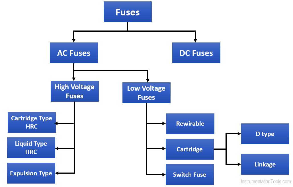
Types of Fuses based on the circuit:
There are many types of fuses available for various applications. The main category of fuses is based on the type of circuit they are used for.
DC Fuses:
The main difference between AC and DC fuses is the size of the fuse. They operate for a constat voltage above zero volts and due to this there will be arcing inside the DC fuses.
AC fuses:
AC fuses are small in size. They operate by alternating voltage with a varying frequency of 50 cycles or 60 cycles per second.
Source: Wikipedia, electronics hub.
Interest to add any further points? Share with us through below comments section.
If you liked this article, then please subscribe to our YouTube Channel for PLC and SCADA video tutorials.
You can also follow us on Facebook and Twitter to receive daily updates.
Read Next:


Very nice subject