Unfortunately, most of us are getting stuck when faults occurred in an Automation system and you might be confused about the exact reason for the fault.
So, today and by the deep understanding of this article, we will learn How to identify clearly the main reason for the fault as fast as possible whether it is a software fault (like PLC coding faults) or a circuit design hardware fault.
By using a critical tool which is the PLC Indicators.
What is meant by a SCADA System?
Before we get to our topic, we have to understand clearly the function of the SCADA system.
SCADA as a word Stands for Supervisory Control and Data Acquisition.
Assume that you are controlling a Factory that contains many electrical devices and uses many MCC panels (Motor Control Center panel) and also various types of sensors like (temperature and pressure transmitters).
So, in such a situation you need a huge number of operators to monitor all of this equipment because they are very critical and one mistake can make a serious problem.
Instead of using many operators, simply you can draw a graphical representation for all your factory that allows and help you to convert the physical components and equipment of your plant to a tiny SCADA software.
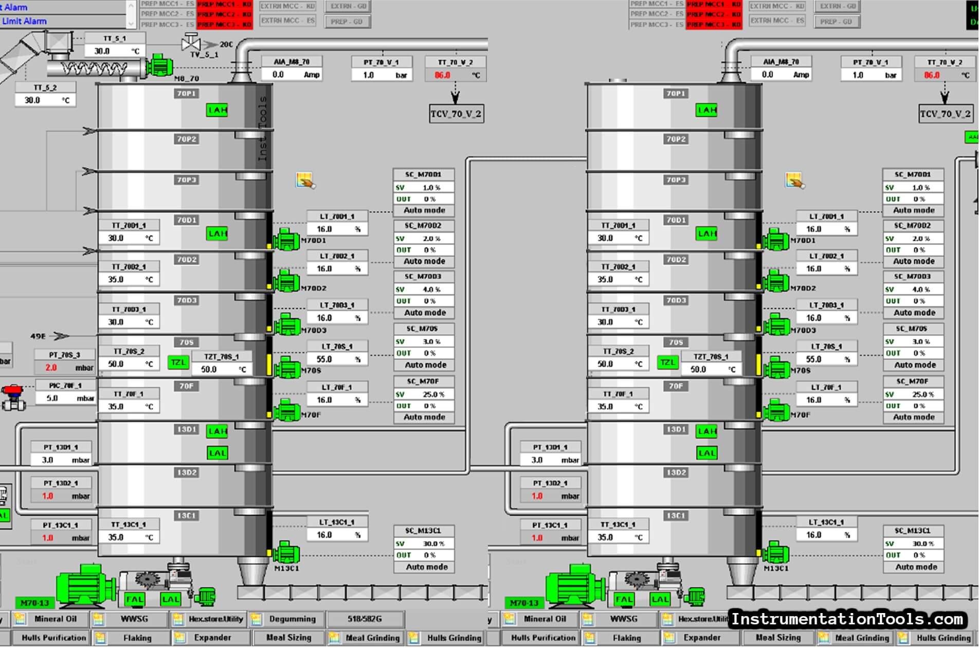
This SCADA system will allow you to monitor and control your factory without the need for many operators as all of your Motors and Indicators will be controlled using a single screen that is operated by a single person.
PLC Status and Troubleshooting Via Indicators
PLC status and diagnostic indicators can be organized according to the type of module on which they reside:
- Discrete Input Module Indicators
- Discrete Output Module Indicators
- Processor Module Indicators
- Power Supply Indicators
Function of Input & Output PLC Indicators
The indicators on most Siemens input modules are used to indicate the input is receiving an input voltage or not.
Some S7-300 modules have built-in diagnostic capabilities. These modules include an SF indicator that illuminates red when an error is sensed by the module
The indicators on most Siemens output modules, illuminate green to indicate whether the output is supplying a voltage or not. Some S7-300 output modules have built-in diagnostic capabilities.
These modules include an SF indicator that illuminates red when an error is sensed by the module
The difficult issue of dealing with huge systems
As all of us know the more your system or plant gets bigger, the more will be difficult to troubleshoot.
One of the most problems that you will face by dealing with big plants is to know if the fault is in the code conditions (software) or it is in the control circuit of the equipment.
Example
Assume that we have a faulty motor called MT5715BC as we can see in the next AFD (Automation Functional Description) Fig. (2) all of these conditions must be achieved to turn on this motor.
All of these conditions are being translated into programming instructions, so instead of going Online through the PLC trying to figure out if there is an error in the code or not.
| MT5715BC | |||
| Main | Sub | ||
| 704 control sequence instep PRODUCTION | X | ||
| and | YAO T57168C not in alarm | X | |
| and | LAH 730F-1 not in alarm OR VHL WT 730F-1 = FALSE | X | |
| and | SAL T5715BC-1 Not in alarm (inhibited at start for 5 sec) | ||
| and | MT5715BC Not in thermal overload alarm |
Simply you can use the PLC indicators
All you need to do is to find the exact Output address that is responsible for turning on this motor.
You can get this address from the wiring of the MCC panel.
Once you know the desired address, you can go to your panel and use the output card indicators that are shown in Fig. (3) to know if the PLC has activated the specified address or not.
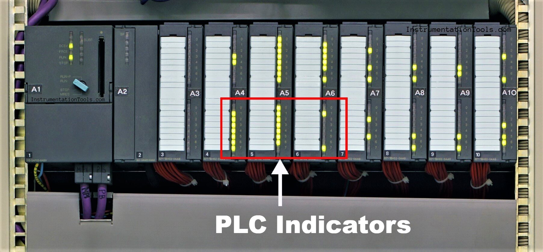
If the PLC has activated the specified address indicator that means all of the instructions are achieved which means the conditions also are presented.
So, definitely, you will find the fault in the Motor Control Circuit and you can use this article to know How to Troubleshoot Control Circuits.
Elseif {… The specified address indicator is not activated this means that there are obstacles (conditions) in the programming code that prevent it from activating the output.
So, in this situation, you have to ensure again that all of the motor conditions are achieved.
Troubleshoot the Status of a PLC Via CPU Indicators
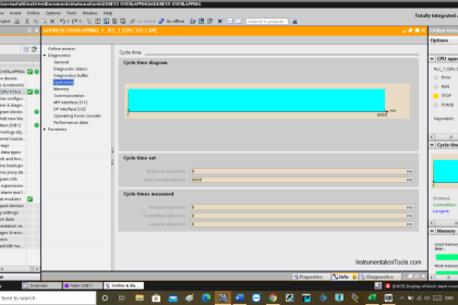
The S7-315-2PN/DP processor (CPU) provides six basic indicators, as shown in Fig. (4).
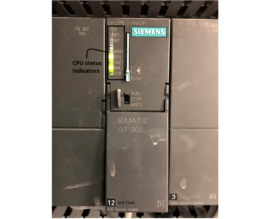
We use these indicators to understand the function and status of the processor module, a good troubleshooter should also know the probable cause and action required to clear the fault.
The next table shown in Fig. (5) lists the probable causes and actions required to clear faults associated with the processor’s status indicators.
| INDICATOR | STATE | STATUS | RECOMMENDED ACTION |
| SF | Off | No software or hardware error is present. | No action is required. |
| SF | Red | A hardware or software error is detected in the system. | Go online with the processor. Use the software to try to determine the cause of the fault. |
| BF | Off | No bus fault is detected. | No action is required. |
| BF | Red | A bus fault has been detected in the system. | Troubleshoot the processor. Troubleshoot the Profibus network. |
| DC5V | Off | 5VDC power for the CPU and S7-300 bus is faulty. | Troubleshoot the power supply circuitry. |
| DC5V | Green | 5VDC power for the CPU and S7-300 bus is ok. | No action is required. |
| FRCE | Off | No forces are enabled in the processor. | No action is required. |
| FRCE | Yellow | One or more input or output addresses have been forced to an On or Off state and enabled. | Monitor the program online and identify the forced I/O. Disable the forces and test operation again. |
| RUN | Off | The processor is either off, or in STOP mode. | Use the mode selector switch to place the processor into Run mode. |
| RUN | Green | The processor is in RUN mode. | No action is required. |
| STOP | Off | The processor is either off, in RUN mode, or in RUN-P mode. | No action is required. |
| STOP | Yellow | The CPU is in STOP mode. | Use the mode selector switch to place the processor into RUN mode. |
| STOP | Flashing Yellow | The CPU is in either Startup or Reset mode. | Allow the startup or reset to complete. |
By following these inputs, we can understand the fault in the PLC system and implement the respective troubleshooting action to solve the problem.
If you liked this article, then please subscribe to our YouTube Channel for Electrical, Electronics, Instrumentation, PLC, and SCADA video tutorials.
You can also follow us on Facebook and Twitter to receive daily updates.
Read Next:
- Ladder Logic Example
- WinCC Runtime Advanced
- Why 24 Volts DC Power Supply?
- Communication in S7-1200 PLC
- Factory Acceptance Test of PLC


I think the information is not clear, is there is any indicator in the HMI that indicates the status of I/P& O/P signals,
The term address is normally used in this field as binary coding number , it has been mentioned here to identify the wiring ????
Hi Amin,
Hope you are doing great.
Of course, there are some indicators in the HMI application but that is not the post scope.
The scope of the post is to use the indicators of the PLC (as hardware).
The term “address” refers to the exact bit of the output card.
This bit could be known from the wiring diagram.
You can check this post “How to Troubleshoot Control Circuits” it will help you to identify these addresses from the wiring.