Inst ToolsInst ToolsInst Tools
  • Courses
  • Automation
    • PLC
    • Control System
    • Safety System
    • Communication
    • Fire & Gas System
  • Instrumentation
    • Design
    • Pressure
    • Temperature
    • Flow
    • Level
    • Vibration
    • Analyzer
    • Control Valve
    • Switch
    • Calibration
    • Erection & Commissioning
  • Interview
    • Instrumentation
    • Electrical
    • Electronics
    • Practical
  • Q&A
    • Instrumentation
    • Control System
    • Electrical
    • Electronics
    • Analog Electronics
    • Digital Electronics
    • Power Electronics
    • Microprocessor
  • Request
Search
  • Books
  • Software
  • Projects
  • Process
  • Tools
  • Basics
  • Formula
  • Power Plant
  • Root Cause Analysis
  • Electrical Basics
  • Animation
  • Standards
  • 4-20 mA Course
  • Siemens PLC Course
Reading: How to make RJ45 cable
Share
Notification Show More
Font ResizerAa
Inst ToolsInst Tools
Font ResizerAa
  • Courses
  • Design
  • PLC
  • Interview
  • Control System
Search
  • Courses
  • Automation
    • PLC
    • Control System
    • Safety System
    • Communication
    • Fire & Gas System
  • Instrumentation
    • Design
    • Pressure
    • Temperature
    • Flow
    • Level
    • Vibration
    • Analyzer
    • Control Valve
    • Switch
    • Calibration
    • Erection & Commissioning
  • Interview
    • Instrumentation
    • Electrical
    • Electronics
    • Practical
  • Q&A
    • Instrumentation
    • Control System
    • Electrical
    • Electronics
    • Analog Electronics
    • Digital Electronics
    • Power Electronics
    • Microprocessor
  • Request
Follow US
All rights reserved. Reproduction in whole or in part without written permission is prohibited.
Inst Tools > Blog > Common > How to make RJ45 cable

How to make RJ45 cable

Last updated: December 17, 2017 1:29 pm
Editorial Staff
Common Guest Articles
4 Comments
Share
4 Min Read
SHARE

RJ45 cable is used for connect the ALL HMI and engineer station through a switch to communicated each other. It is used to download the any modification and which is made in graphics in engineering station.RJ45 cable also used for communicate the printer with computer.

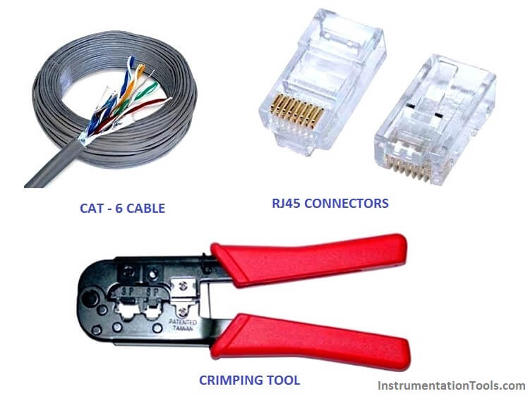
Required tool and materials:

  1. Ethernet Cable – Category 5e or CAT5e or CAT6
  2. RJ-45 Crimping tool
  3. RJ45 Crimp able Connectors

RJ45 Cable

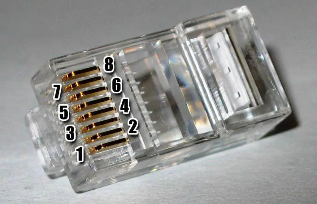
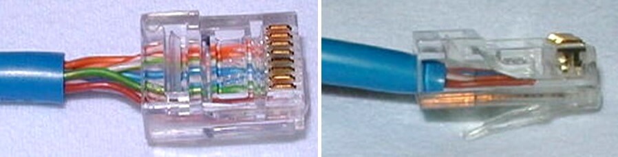
Introduction: There are four pairs of wires in an Ethernet cable, and an Ethernet connector (8P8C) has eight pin slots. Each pin is identified by a number, starting from left to right, with the clip facing away from you.

RJ45 Connector Pins

RJ45

There is two kinds of Ethernet cable is used for communication.

  1. Straight Through
  2. Cross over cable

Straight Through cable: 

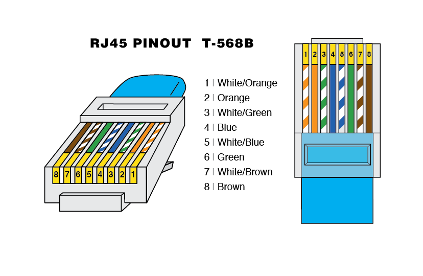
STRAIGHT THROUGH Ethernet cables are the standard cable used for almost all purposes, and are often called “patch cables”. It is highly recommend you duplicate the color order as shown on the left. Note how the green pair is not side-by-side as are all the other pairs. This configuration allows for longer wire runs.

Ethernet Cable RJ45

Important Instruction: Always remember that both end connector clip facing away from you when check the color.

CROSSOVER CABLES –

The purpose of a Crossover Ethernet cable is to directly connect one computer to another computer (or device) without going through a router, switch or hub.

Ethernet RJ45 CrossOver Cable

Procedure to make RJ45 cable :

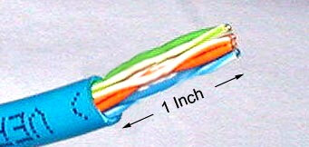
Step 1: Cut into the plastic sheath about 1 inch (2.5 cm) from the end of the cut cable. Do not cut deep which may cause damage the insulation of core.

Ethernet Cable cut

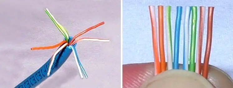
Step 2: Unwind and pair the similar colors. Pinch the wires between your fingers and straighten them out in a sequence of color as u want to make cable (Straight cable or cross over cable). The color order is important to get correct

Ethernet Cable Crimping

Step 3: A straight cut across the 8 wires to shorten them to 1/2 Inch (1.3 cm) from the cut sleeve to the end of the wires by crimping tool. Carefully push all 8 unstrapped colored wires into the connector. Plastic sleeve should be inserted proper in connector.

Ethernet Cable Making

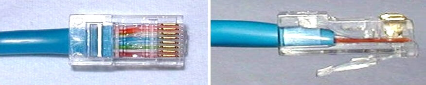
Wrong way: The plastic sleeve is not inside the connector where it can be locked into place. The wires are too long. The wires should extend only 1/2 inch from the blue cut sleeve. The wires do not go all the way to the end of the connector. The wires are too short.

Ethernet Cable Making - 2

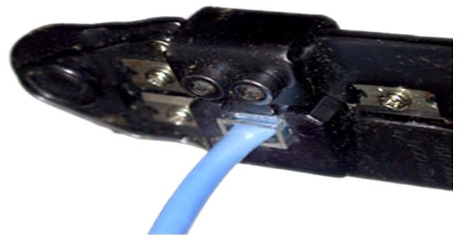
Crimping the cable: Carefully place the connector into the Ethernet Crimper and cinch down on the handles tightly. The copper splicing tabs on the connector will pierce into each of the eight wires. There is also a locking tab that holds the plastic sleeve in place for a tight compression fit. When you remove the cable from the crimper, that end is ready to use.

Ethernet Cable Crimping Tools

Test the cable: Check the continuity of both connectors each other .Check the cable threw a cable tester or ping from a computer. To check the cable through computer connects both connector in two computers for cross cable and straight cable connect through a switch then ping the computer.

Source : groundcontrol

Article by :
Ashish Agrawal
Don't Miss Our Updates
Be the first to get exclusive content straight to your email.
We promise not to spam you. You can unsubscribe at any time.
Invalid email address
You've successfully subscribed !

Continue Reading

Batch Pan Automation in the Sugar Industry
Electrification in Mining Industry
Basic Principles of Solar Technology
What is Hot Air Welding? – Advantages
Computer Science and Technology Majors Certifications
Difference between Electron and Proton
Share This Article
Facebook Whatsapp Whatsapp LinkedIn Copy Link
Share
4 Comments
  • Robert Davis says:
    January 5, 2018 at 6:51 am

    These are very useful information for making RJ45. RJ45 connectors is a standardized physical network interface for connecting telecommunications or data equipment. Thanks for sharing..!!

    Reply
  • Todd E. Boyett says:
    May 25, 2018 at 1:10 am

    Really helping article to crimping an RJ45 Connector correctly proper wiring for Ethernet Cables Cat5/Cat5e or Cat6 Cables. Thanks for the information. It was helpful for crimping several connectors today.

    Reply
  • Jason Smith says:
    May 31, 2018 at 2:45 am

    Very useful article for people who are usually confused about some technical terms and installation procedures. Thanks for sharing it.
    It would be a pleasure to share that http://www.bncables.com is helping people for a good ethernet future. Ask or get any kind of information about ethernet cables.

    Reply
  • Jhon says:
    November 14, 2020 at 3:07 am

    Rj45 is the key for successful Ethernet.

    Reply

Leave a Reply Cancel reply

Your email address will not be published. Required fields are marked *

Stay Connected

128.3kFollowersLike
69.1kFollowersFollow
210kSubscribersSubscribe
38kFollowersFollow

Categories

Explore More

How does the IIoT work? – Industrial Internet of Things
Level Measurement and Control using Arduino C
Types of Signals Based on Electromagnetic Compatibility (EMC Performance)
Practical Pneumatic Instruments
Pirani Gauge Working Principle
Difference Between Belt Conveyor and Roller Conveyor
How to Do Linear Programming in Excel?
Piezo-electric Acceleration Measuring Device

Keep Learning

Sheet Metal Fabrication Manufacturing and Design

Ideal Guide To Sheet Metal Fabrication Manufacturing and Design

Swiss Screw Machining

Things You Should Know About Swiss Screw Machining

Pipeline Pig Detector

What are Non-Intrusive Pig Signallers or Pig Detectors?

Difference Between Predictive Maintenance and Preventive Maintenance

Difference Between Predictive Maintenance and Preventive Maintenance

Evolution of Air Compressors

The Evolution of Air Compressors: From Power to Silence

Digital Instrument Example

Digital Measuring Instruments – Types, Functions, Advantages, Disadvantages

MEASURING AN NPT CONNECTION

NPT Connection Measurement Size

Laser Cutting Precision and Accuracy

Benefits of Steel Laser Cutting

Learn More

Analyzers Questions and Answers

Analyzers Based on Gas Density Questions & Answers

Inspection and Testing of Fiber Optic Cable

Inspection and Testing of Fiber Optic Cable

Industrial Gases

Questions and Answers on Gas

Two Out of Three Logic

Alarm and Trip Systems

Process Shutdown

Difference between Process shutdown and Emergency Shutdown

Power Supply Sizing for Industrial Automation Systems

Power Supply Sizing for Industrial Automation Systems

Digital Electronics Multiple Choice Questions

Shift Register Counters Objective Questions

Parameters of SRT_DINT instruction

Tia Portal – OB20 Time Delay Interrupt Organization Block

Menu

  • About
  • Privacy Policy
  • Copyright

Quick Links

  • Learn PLC
  • Helping Hand
  • Part Time Job

YouTube Subscribe

Follow US
All rights reserved. Reproduction in whole or in part without written permission is prohibited.
Welcome Back!

Sign in to your account

Username or Email Address
Password

Lost your password?