Inst ToolsInst ToolsInst Tools
  • Courses
  • Automation
    • PLC
    • Control System
    • Safety System
    • Communication
    • Fire & Gas System
  • Instrumentation
    • Design
    • Pressure
    • Temperature
    • Flow
    • Level
    • Vibration
    • Analyzer
    • Control Valve
    • Switch
    • Calibration
    • Erection & Commissioning
  • Interview
    • Instrumentation
    • Electrical
    • Electronics
    • Practical
  • Q&A
    • Instrumentation
    • Control System
    • Electrical
    • Electronics
    • Analog Electronics
    • Digital Electronics
    • Power Electronics
    • Microprocessor
Search
  • Books
  • Software
  • Projects
  • Process
  • Tools
  • Basics
  • Formula
  • Power Plant
  • Root Cause Analysis
  • Electrical Basics
  • Animation
  • Standards
  • 4-20 mA Course
  • Siemens PLC Course
Reading: #3 PLC Best Practices – Leave Operational Logic in the PLC wherever feasible
Share
Notification Show More
Font ResizerAa
Inst ToolsInst Tools
Font ResizerAa
  • Courses
  • Design
  • PLC
  • Interview
  • Control System
Search
  • Courses
  • Automation
    • PLC
    • Control System
    • Safety System
    • Communication
    • Fire & Gas System
  • Instrumentation
    • Design
    • Pressure
    • Temperature
    • Flow
    • Level
    • Vibration
    • Analyzer
    • Control Valve
    • Switch
    • Calibration
    • Erection & Commissioning
  • Interview
    • Instrumentation
    • Electrical
    • Electronics
    • Practical
  • Q&A
    • Instrumentation
    • Control System
    • Electrical
    • Electronics
    • Analog Electronics
    • Digital Electronics
    • Power Electronics
    • Microprocessor
Follow US
All rights reserved. Reproduction in whole or in part without written permission is prohibited.
Inst Tools > Blog > PLC Tutorials > #3 PLC Best Practices – Leave Operational Logic in the PLC wherever feasible

#3 PLC Best Practices – Leave Operational Logic in the PLC wherever feasible

Leave as much operational logic e.g., totalizing or integrating, as possible directly in the PLC. The HMI does not get enough capacity.

Last updated: September 21, 2021 1:03 am
Editorial Staff
PLC Tutorials
No Comments
Share
5 Min Read
SHARE

Leave as much operational logic e.g., totalizing or integrating, as possible directly in the PLC. The HMI does not get enough updates to do this well.

Contents
Leave Operational Logic in the PLCExample
Security ObjectiveTarget Group
  The integrity of PLC logicProduct Supplier Integration / Maintenance Service Provider Asset Owner

Leave Operational Logic in the PLC

HMIs provide some level of coding capabilities, originally aimed to help operators enhance visualization and alarming, that some programmers have employed to create code that should rather stay in the PLC to remain complete and auditable.

Calculating values as close to the field as possible makes these calculations more accurate. The HMI does not get enough updates to do totalizing / integrating well.

Also, there is always latency between HMI and PLC. Further, when the code is in the PLC, and an HMI restarts, it can always receive totalizers/counts from a PLC.

In particular, HMI code to be avoided is anything related to security or safety functions such as interlocks, timers, holds or permissives.

For analyzing process data values over time, a process data historian is a better choice than the HMI. Use queries in a process historian database to compare totalized values (over a period, over a batch, over a process cycle) with totals aggregated locally in PLC logic.

Alert on a variance greater than that can be explained by differences in data granularity.

Leave Operational Logic in the PLC

Example

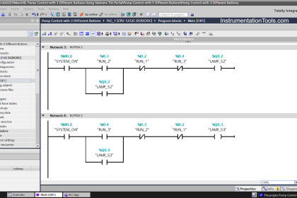
Code to establish conditions to enable/disable buttons: Enable/disable actions should be controlled on the PLC layer, otherwise, actions can be performed on the HMI (or through the network) in PLC, although not meeting (intended) conditions.

Timers to allow actions to the operator (delay timer for consecutive motor starts, timer to consider valves closed/open or motor stopped) should not be put on the HMI layer but in the PLC governing such motor/valve.

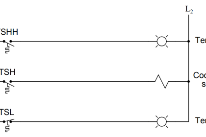
Thresholds for alarms have to be part of PLC codes although displayed on HMIs.

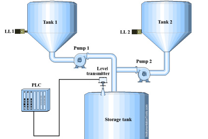
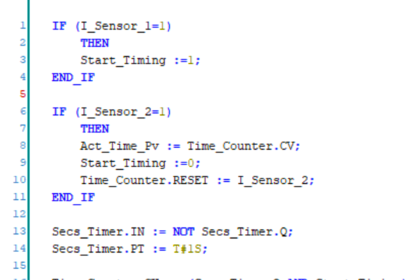
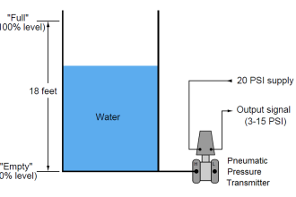
Water tank with changing volume: The PLC which controls flow in and out of the tank can easily totalize volume (and cross-validate totals).

The HMI could do this as well, but it would need to get the values from the PLC first. These values would need accurate time-stamps in order to get correct totals in case of latency or and might miss values if the HMI restarts.

Why?

Beneficial for…?Why?
Security1. Allows consistency in verifying code changes. HMI coding has its change control apart from PLC, generally not with the same rigor (especially in construction and commissioning phases), not allowing system owners to have a complete view, and even losing important considerations.

HMI’s do not include “forced signals” or changed value lists as PLCs or SCADAs, so HMI level changes are more difficult to be detected, practically impossible to be part of an authorization change management plan.

2.   For an attacker, it is harder to manipulate totals distributed over many PLCs than to manipulate totals all calculated in the HMI.

3.   If a portion of the enable/disable functions are not in the PLC, attackers might be able to manipulate the PLC and I/O without having to work the HMI portion as the proper information is already obfuscated on the operator screen.
            Reliability1.   Calculations are more efficient and accurate if closer to the field. Also, totals and counts will still be available if HMI restarts (PLCs do not restart as often and usually store these values in non-volatile memory).

2.   Different sources for inputs and interlocks may mean non-expected failures. There can be different technologies for HMIs in a plant (SCADA layer, but also field controller panels), and changes in one of those will fail to be disseminated through the rest of the layers, leading to inconsistencies in visualization and possible failures in operation.
  MaintenanceCoding is easy to understand and transfer from PLC to PLC, not so much from HMIs to HMIs.

References

Standard/frameworkMapping
  MITRE ATT&CK for ICSTactic:  TA010 – Impair Process Control
Technique:  T0836 – Modify Parameter
ISA 62443-3-3SR 3.6: Deterministic Output
ISA 62443-4-2CR 3.6: Deterministic Output

Source: PLC Security

Don't Miss Our Updates
Be the first to get exclusive content straight to your email.
We promise not to spam you. You can unsubscribe at any time.
Invalid email address
You've successfully subscribed !

Continue Reading

Example of PLC Programming based on Logic Circuit
Top Free PLC Software
How to Use the Shift and Rotate Instructions in PLC?
PLC Program for Bank Counter Application
Establish Communication Between Two PLC Via PROFIBUS Protocol
PLC Analog I/O and Network I/O
Share This Article
Facebook Whatsapp Whatsapp LinkedIn Copy Link
Share
Leave a Comment

Leave a Reply Cancel reply

Your email address will not be published. Required fields are marked *

Stay Connected

128.3kFollowersLike
69.1kFollowersFollow
208kSubscribersSubscribe
38kFollowersFollow

Categories

Explore More

SFC Language in PLC Programming
PLC Programming Example on LED Control
SCADA Engineer Job Responsibilities and Skills
OMRON PLC Tutorial: Car Parking System Application
How to Add Unspecified CPU in Tia Portal?
Configuration of Input and Output Tags in Siemens Scada and PLC
PLC Program to Simulate Gate Array Logic
How to use Masked Move Instruction in PLC

Keep Learning

Latching and Unlatching in PLC Programming for Beginners

Latching and Unlatching in PLC Programming Example

Difference Between Industrial Computer and Normal Computer

Difference Between Industrial Computer (IPC) and Normal Computer (PC)

OpenPLC - PLC Training for Students - Free Tutorials & Courses

OpenPLC – PLC Training for Students – Free Tutorials & Courses

PLC Logic Example on Multiple Switches and Motors

PLC Logic Example on Multiple Switches and Motors

S7 Organizational blocks

Siemens PLC Tia Portal – OB100 Start-up Organization Block

Industrial motor control using PLC instruction list programming

PLC Instruction List for Motor Reverse and Forward Direction

Industrial Automation and Control Systems (IACS)

Industrial Automation and Control Systems (IACS)

PLC Automatic Pedal Switch for Speed Control

PLC Automatic Pedal Switch for Speed Control

Learn More

Turbine Flow Meter Calibration

How to do Turbine Flow Meter Verification?

Machine Learning

Difference Between Machine Learning and Artificial Intelligence?

Single-Bed Demineralizer

Demineralizers

Electronic Devices & Circuits Objective Questions

Electronic Devices & Circuits Quiz – Set 4

Microprocessors Objective Questions

Microprocessors Objective Questions – Set 2

Ladder Logic Example with Timers

Ladder Logic Example with Timers

Radiometric level Principle

Radiometric level measurement Working Principle

How to Run Multiple Motors with a Single VFD

How to Run Multiple Motors with a Single VFD?

Follow US
All rights reserved. Reproduction in whole or in part without written permission is prohibited.
Welcome Back!

Sign in to your account

Username or Email Address
Password

Lost your password?