In this article, we discussed the Yokogawa DCS system maintenance procedures.
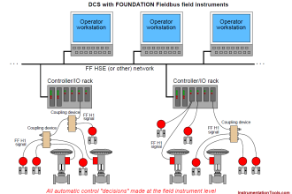
Here we covered the Yokogawa Centum VP distributed control system checks which include field control station, server, power supply modules, CPU battery, HIS engineering and operator stations, Sequence of Events (SOE) server, OPC Server, the plant resource manager (PRM), redundancy checks, Node interface unit, ESB bus, Vnet IP, and IO modules.
Test Equipment
- Hand tools,
- Digital Multimeter.
General Checks of FCS
Here FCS stands for Field Control Station in Yokogawa Centum VP DCS system.
We will do the general checks of FCS on a monthly basis.
- Domain Number and its healthiness.
- FCS Number and its healthiness.
- HIS Number and its healthiness.
- Integrated system and its healthiness check.
The below list shows some of the integrated systems in a DCS system.
a. Prosafe RS system
b. PRM
c. OPC Server
d. SOE Viewer
e. Time master HIS0364
DCS Project Details Checks
We will do the project details checks on a monthly basis.
- Project Name
- Project Size in GB
- Project Path
- Set back path
- CENTUM VP project software application backup in media (DVD, external HDD)
DCS Server System Environment Checks
We will do the DCS server system environment checks on a weekly basis.
- Room temperature
- Relative humidity
- Dust deposition or Ingress
Yokogawa DCS System
We will do the field control station checks on a monthly basis.
- Model Number and serial number
- Number of nodes
- Communication load average
- Tuning parameters saving successful
- CPU idle time
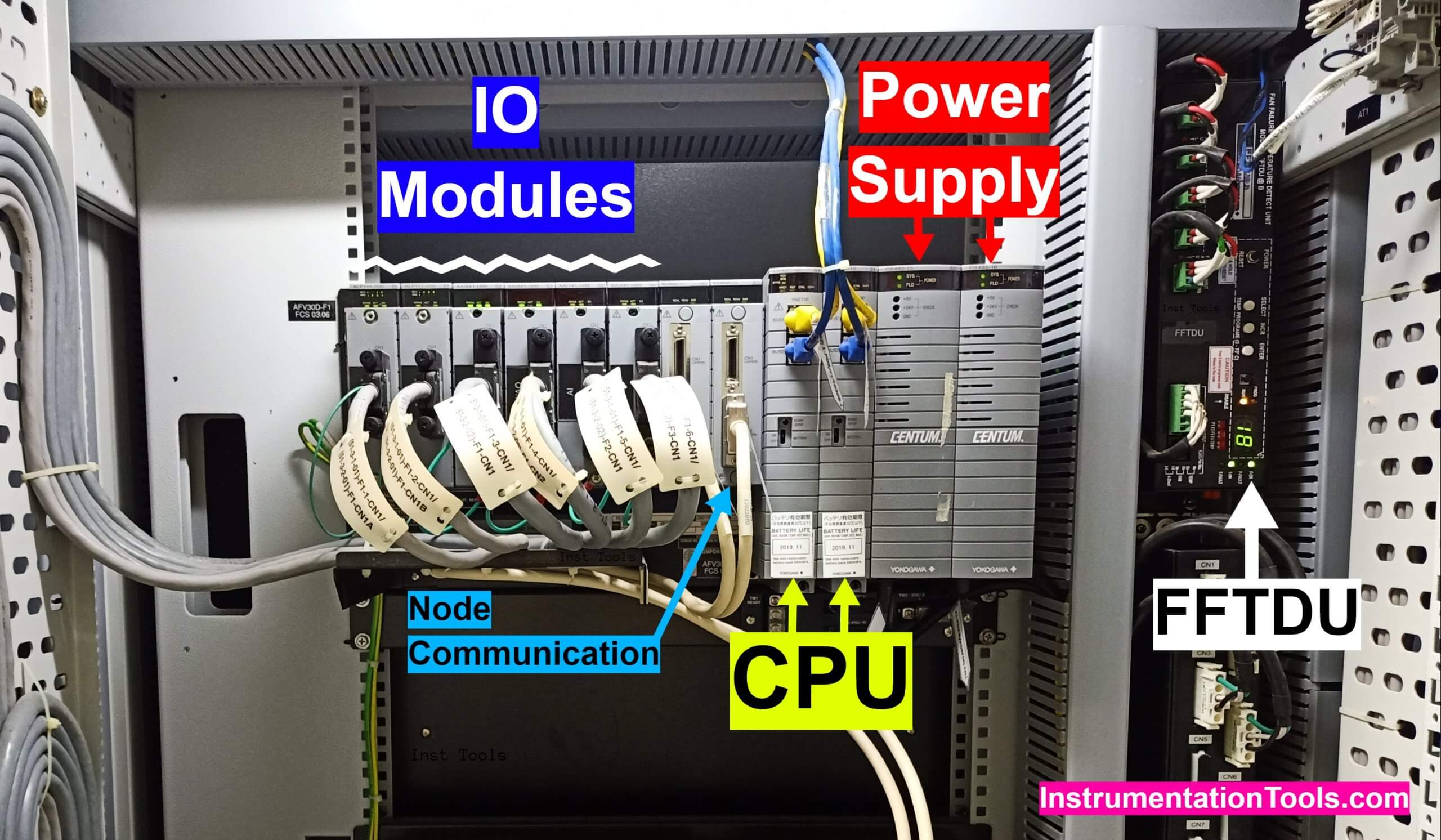
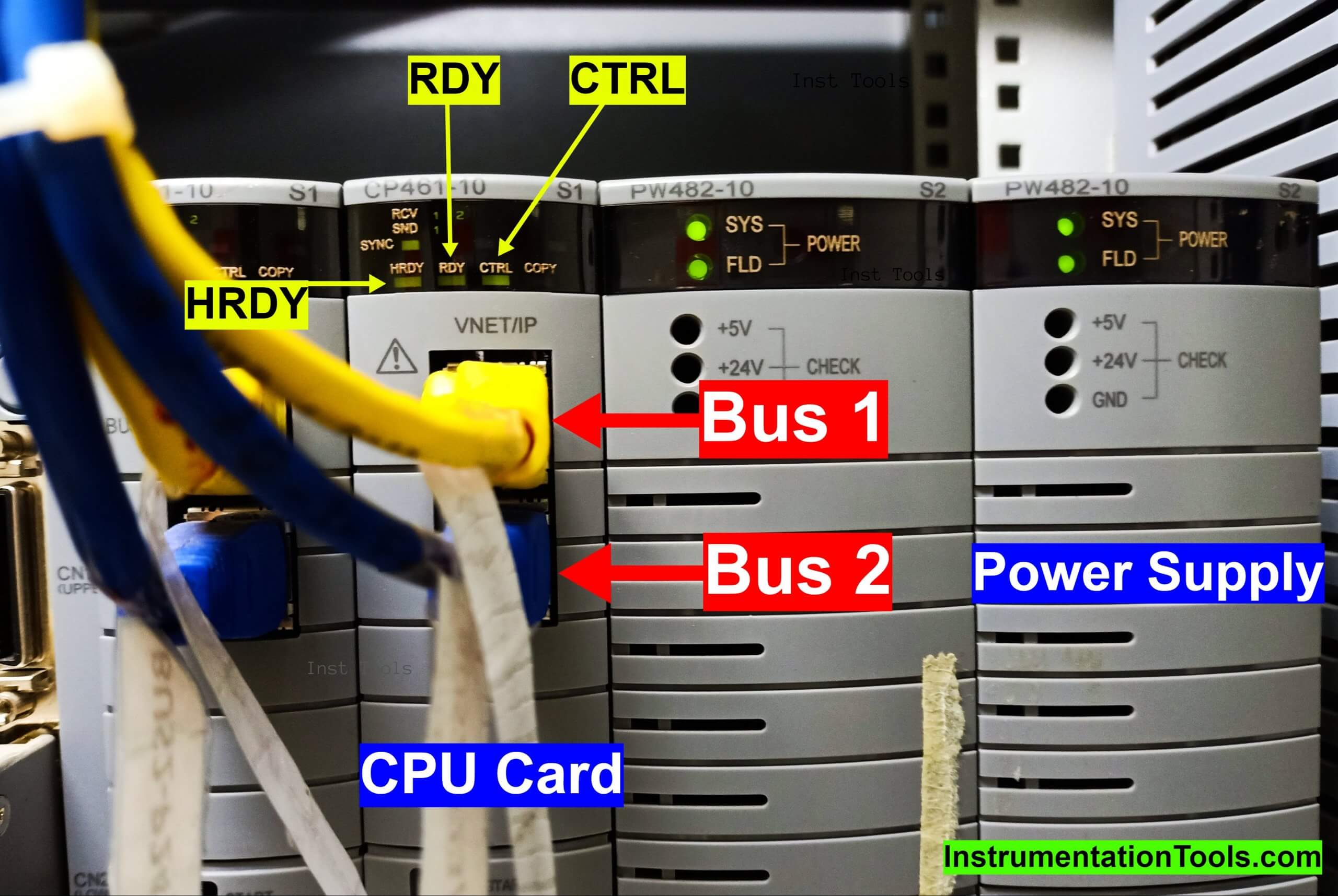
- Visual checks of all cards (CPU, CP, PS, ESD, IO, Terminal board etc.)
- Vnet/IP bus status
- FFTDU status (Fan Failure and Temperature Detection Unit)
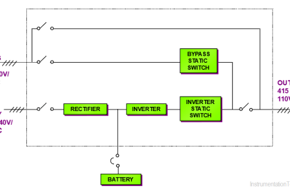
Power Supply and other Checks
We will do the power supply and other checks on a monthly basis.
- Measure L-N, L-E & N-E AC voltages of both Left & Right feeders from UPS.
- Measure DC voltage for both Left & Right feeder supply.
- Measure DC voltage at Analog and Digital terminal board.
- Proper grounding and welding of panel.
- Proper earthing of panel, instrument earthing.
- FAN status.
- Panel Filter status.
- Room temperature
- Relative humidity
- Dust deposition or ingress
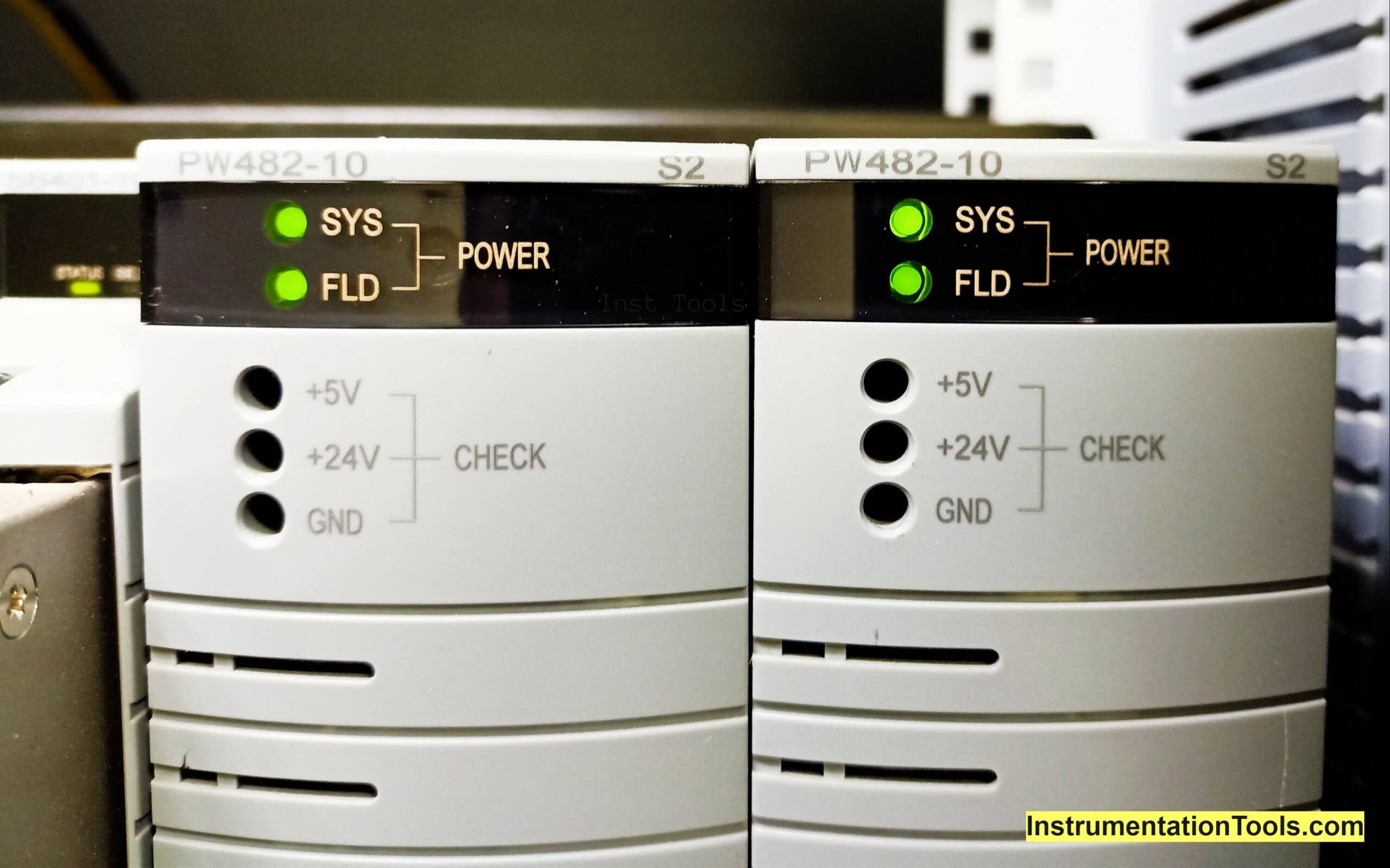
CPU Battery & PW482 Checks
We will do the CPU battery & PW482 checks on a quarterly basis.
- Battery expiry date of Left & Right CPUs.
- Measure Voltages of Left & Right CPU Battery.
- Measure voltages of PW482, at all left and right nodes.
HIS Engineering and Operator station, SOE Server, OPC Server, PRM checks
We will do the HIS Engineering and Operator station, SOE Server, OPC Server, PRM checks on a monthly basis.
- Domain, Station Number
- Model, Serial Number
- Visual checks
a. VI701 network card
b. Event viewer status
c. FAN status
d. CPU performance
e. Hardware healthiness
- Vnet/IP Bus 1 & 2 IP address, subnet mask, default gateway
- Server PC OS and service pack details
- Server Antivirus license and patch update status
- CENTUM VP license ID checks.
- Server RAM, virtual memory size, hard disk size and free space.
- Data storage device floppy drive, DVD drive, DAT drives status.
- Equalize to all HIS.
- CENTUM VP project application backup status.
- Report generation, alarm and trend status checks
- PRM, field instrument on network and data read & write status.
- HIS input power L-N, L-E, N-E.
Redundancy Checks of Power Supply Module
We will do the redundancy checks of the power supply module on a yearly basis.
The purpose of this test is to verify the CPU is not affected if any one of the node power supply fails.
- Switch off all left/right sides of power supply module by switching off the corresponding MCB.
- Check system alarm message displayed on the operator station (HIS) and the Station status display window in ENGG/HIS.
- Check for any spurious action in I/O modules.
- Repeat the above steps for both of power supply modules.
- Remember, the other power supply module will still function normally as observed in the Station Status Display in operator station (HIS).
Ready lamp on the CPU will still be ÖN”. No spurious action should be observed at the I/O during the test.
Redundancy Checks of 24V DC Power Supply Unit
We will do the redundancy checks of the 24 volts dc power supply unit on a yearly basis.
- Check that failure of one power supply does not affect the terminal and the relay board.
- Switch off anyone incoming 24V DC MCB to the Diode ’O’ ring unit in marshalling cabinet.
- Check if the relays and terminal board’s power is not interrupted in marshalling cabinet.
- Repeat the same for other 24V DC MCB to the Diode ’O’ ring unit.
Redundancy Checks of CPU
We will do the redundancy checks of the Yokogawa distributed control system CPU on a yearly basis.
Test 1
The purpose of this test is to ensure that all components automatically boot up when going from a ‘stop’ environment to an ‘operating environment.
a. ‘Power on’ each component individually. ‘Power off’ all the components individually.
b. Each component boots up automatically. System start time will be displayed on the System Alarm Panel of the HIS which is not currently under test.
Test 2
The purpose of this test is to verify that the standby CPU becomes ‘active’ when the active CPU fails and that all loop data remains the same after switchover.
The control shall be transferred promptly and correctly to the standby CPU as observed through the “Control Station Status Panel” displayed on the ENGG station and operator station (HIS). No spurious action should be observed at the I/O during the test.
a. Stop the active CPU by activating the START/STOP button.
b. Check the system alarm messages displayed on the operator station (HIS) and the Station Status Display.
c. Repeat 1 & 2 for other CPUs after the FCS resumes from COPY mode.
d. Repeat the above procedure for other FCS CPUs in the network.
e. Check for any spurious action in I/O in the trend panel.
Redundancy Checks of Power Supply Module of Node Interface Unit (NIU)
We will do the redundancy checks of the power supply module of the node interface unit (NIU) on a yearly basis.
The purpose of this test is to verify that the NIU is not affected if any one of the node power supply modules fails.
Switch off all left/right sides of the power supply module by switching off the corresponding MCB.
Check system alarm message displayed on the operator station (HIS) and the Station Status Display window in ENGG/HIS.
Check for any spurious action in I/O.
Repeat the above for both sides of the power supply modules.
Remember, the other power supply module will still function normally as observed in the Station Status Display in Operator Station (HIS). Ready lamp on each I/O card will still be ‘ON’.
No spurious action should be observed at the I/O during this test. During this test, all the power supply units powered by the respective incoming feeders will be switched off.
Redundancy Checks of Node Interface Unit (NIU) Communication Card FIO
We will do the redundancy checks of node interface unit (NIU) communication card FIO on a yearly basis. Here FIO stands for Fieldnetwork I/O.
The purpose of this test is to verify that the control function is not disrupted even if one of the NIU communication cards (SB401) fails.
Remove one of the NIU communication cards from the slot.
Check the system alarm messages on the operator station.
Note: Use a proper star(+) screwdriver to remove the NIU card
Remember, the other SB401 communication card will work correctly as observed through the “Station Status Display” window.
Redundancy Checks of ESB Bus
We will do the redundancy checks of the ESB bus on a yearly basis.
The purpose of this test is to verify that the control function is not disrupted even if one of the communication modules fails
Remove one of the ESB bus coupler connectors.
Check the system alarm messages on the operator station
Note: Use a proper star (+) screwdriver to remove the NIU card
The other EC401 communication Bus will work correctly as observed through the “Station Status Display” window.
Redundancy Checks of Vnet I/P Bus
We will do the redundancy checks of the Vnet i/p bus on a yearly basis.
The purpose of this test is to ensure that failure of one of the inter-station communication V-net/IP has no effect on the normal highway communication.
- Disconnect anyone V-net/IP Bus (Bus 1).
- Check the system alarm messages display on the operator station HIS and status change in System Status Overview window.
- Force a tag from the HIS and observe the I/O changes.
- Perform the above procedure again with the second bus, after restoring the ‘failed’ bus.
- Check the system alarm messages display on the operator station and status change in System Status Overview window.
- Force a tag from the FCS and observe the I/O change in HIS.
- Remember, the HIS/ENGG station can still monitor the change in data from the Field Control Station (FCS) without any disturbance.
Redundancy Checks of IO Modules
We will do the redundancy checks of the IO modules on a yearly basis.
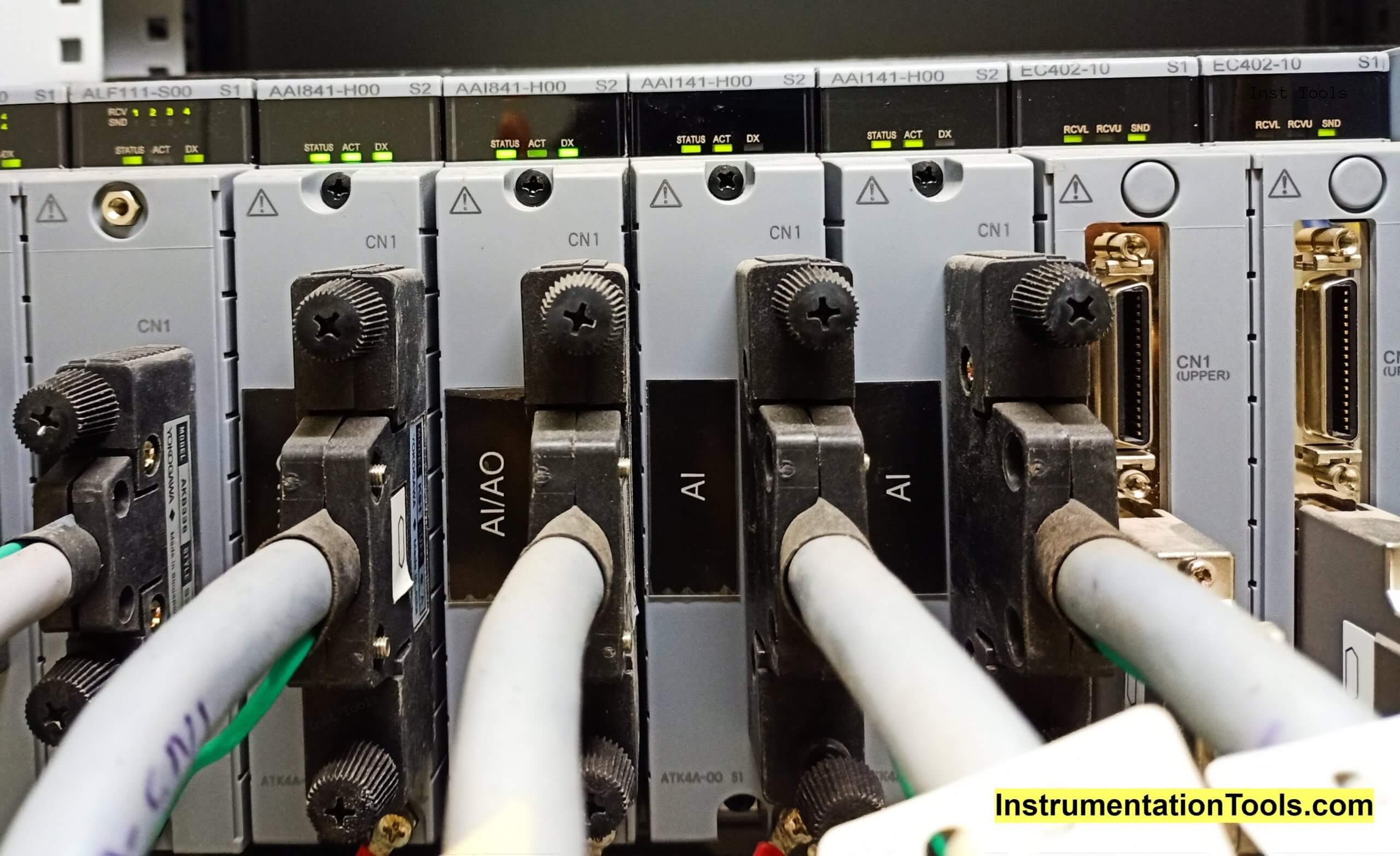
Test 1
The purpose of this test is to verify that the failure of one of the I/O modules does not affect the I/O signals.
a. Select an Analog I/O signal.
b. Monitor the values of a particular tag in HIS.
c. On the Station Status Display window in HIS, check the two modules being displayed in Green and Yellow.
d. Pull the module which is active.
e. Observe the system alarm, the tag value, and the Station Status Display Window in HIS.
Note: Use proper star (+) screw driver.
f. Remember, the System alarm should post the module failure alarm. The Station Status Display Window should show the module status in red, indicating failure and the one that has taken over in green. No change in Tag data should be observed.
Test 2
The purpose of this test is to verify the functionality of the load/save utility in the HIS (with Engineering function), thereby ensuring that the configuration data is transferred via the V-Net/IP.
a. Call up the load/save utility panel in HIS (with Engineering function) and select the Appropriate Field Control Stations (FCS) or Human Interface Stations (HIS).
b. Perform the Load function
c. Perform the Save function.
d. Remember, Loading/ saving of the database should be done without any error messages.
Online Maintenance Function
We will do the online maintenance function checks on a yearly basis.
The purpose of this test is to verify that the Online Maintenance Function is operative.
a. Open a Control drawing for loops or logics.
b. Select a loop or sequence table to be modified
c. Perform modifications as required.
d. Perform Online Download.
e. Ensure that the FCS functionality is uninterrupted.
f. Ensure that the modifications are downloaded to the FCS by doing a functional check of the modifications.
g. Remember, Field Control Stations (FCS) should not stop the normal control/monitoring functions, also the modification made in the database should be reflected correctly in the FCS.
Function Key Assignment Checks
We will do the function key assignment checks on a yearly basis.
The purpose of this test is to verify that the functions of operator keys are navigating to the operator windows correctly as per assigned functions.
Reference: Function key Worksheet filled.
a. Press the Function key on the operation keyboard.
b. Check the respective screen/panel is opened.
c. Confirm that the LED flashes if there is an alarm in the corresponding screen.
d. The navigation of all operator windows is correct with respect to the operation keyboards.
Event Viewer
We will do the event viewer checks on a yearly basis.
The purpose of this test is to verify the functionalities of the package are working correctly.
a. Check the Category Sort window with a display of Status change, Alarm notifies, Alarm recovery, Operation record, and Others.
b. Check the Message display window with a display of all the Historical messages per day in chronological order of time.
c. Check the Point ID Window with the display of tag names along with the number of alarms that had come for that particular tag represented.
Plant Resource Manager (PRM) Checks
We will do the plant resource manager (PRM) checks on a yearly basis.
To demonstrate the basic functions of the PRM components: PRM, Server, PRM Client and Filed Communications Server.
a. Check the Registration of HART devices.
b. Device details update.
c. Device parameter manipulation from PRM, Change the Block Mode of the AI block for one of the devices to out of service and confirm that the alarm appears on the device to ensure communication. Return the block mode of the AI device after the check.
d. Remember, after plug and play operation, Manual Registration all the HART devices, which are in network, and are alive, should appear on the PRM device list respectively.
e. Device details update, after this operation, device details should get updated of PRM.
OPC Communication using Generic Subsystem Gateway (GSGW)
We will do the OPC communication using generic subsystem gateway (GSGW) checks on a yearly basis.
The purpose of this test is to verify that the subsystem signal tags are defined properly in the DCS and its values are updated correctly.
a. Change the tag data of subsystem from the subsystem OPC Server.
b. Ensure that the change is reflected on the DCS side by calling the tag faceplate in the DCS.
c. Check the graphics whether the updating has taken place.
Check for OPC hardware or OPC hardware or OPC link failure alarm by simulating a failure.
Reference: Yokogawa
Interest to add any further checks? Share with us through below comments section.
If you liked this article, then please subscribe to our YouTube Channel for Instrumentation, Electrical, PLC, and SCADA video tutorials.
You can also follow us on Facebook and Twitter to receive daily updates.
Read Next:
- DCS Troubleshooting
- Commissioning of DCS System
- DCS Control System Spares
- Yokogawa DCS Architecture
- DCS System Layout