Override control strategies are a source of much confusion for people who first learning the concept. Perhaps the most fundamental question people find difficult to answer when faced with an override strategy is how to determine the intended purpose for that strategy if no explanation is given.
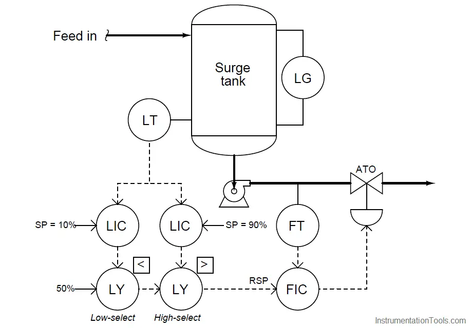
Take for example this surge tank level/flow control system. While it may be obvious that the flow controller is there for the purpose of regulating flow out of the tank, it is not so clear what the two level controllers are doing, or what purposes are served by the two selector functions:
A good starting point in our analysis is to first determine the proper directions of action for each controller. This is wise because the selector functions perform their tasks based on the relative values of the controller output signals: controllers become selected or de-selected on the basis of their output signals being greater or less than some other signal. Therefore, before we may be able to determine the purpose of a selector function, we must know how the loop controller feeding that selector function is supposed to react to process conditions. Once we have determined each controller’s proper action, we may then interpret each selector’s function in light of what process conditions will cause a particular controller to become selected.
When choosing the proper action for each controller, we must consider each controller in this system – one at a time – as though it were the one being selected. In other words, we may give ourselves license to ignore the selector functions and just concentrate for the time being on how each controller needs to act in order to do its job when selected. Looking at the system from this perspective, we see that each level controller (when selected) acts as a master to the flow (slave) controller. Thus, what we have here is a cascade level/flow control system, with two master controllers selected on the basis of their output signals.
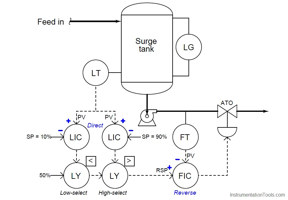
The flow controller (FIC) needs to be reverse-acting, because in order to counter-act an increase in flow rate it must close off the valve (i.e. decreasing output with increasing input = reverse action). Each level controller needs to be direct-acting, because in order to counter-act an increase in level it must call for more flow exiting the tank (i.e. increasing output with increasing input = direct action). Denoting these actions using “+” and “−” labels at each PV and SP input line:
Only now are we prepared to analyze the purpose of each selector function. Let’s begin with the low-select first. It selects the lowest of two values, either a fixed value of 50% or the output of the level controller with the 10% setpoint. Since we know this level controller is direct-acting, we may conclude that it will be selected if it sees a low level at its PV input. More specifically, it will be surely be selected if the measured tank level drops significantly below the setpoint value of 10%. Thus, we may conclude that the purpose of this level controller is to take over control if the tank level reaches or drops below the 10% mark.
Next, let us analyze the purpose of the other level controller (connected to the high-select function). Since the high-select function will select this level controller only if its output signal exceeds the signal passed on by the low-select function, and we know that this controller is direct acting, we may conclude that it will be selected if it sees a high level at its PV input. More specifically, it will surely be selected if the measured tank level rises significantly above the setpoint value of 90%. Thus, we may conclude that the purpose of this level controller is to take over control if the tank level reaches or exceeds the 90% mark.
If neither level controller is selected, the signal that gets passed on to the flow controller as a remote setpoint is the 50% fixed signal entering on the left-hand side of the low-select function. Thus, the flow controller tries to maintain a steady flow rate of 50% in the event neither level controller is selected.
Putting all these pieces together, we may conclude that the purpose of this surge tank control system is to maintain as steady a flow rate as possible out of the tank (and on to some other process), letting the liquid level inside the tank rise and fall significantly before any action is taken to change the flow rate. Only if the level drops below 10% will the flow rate be reduced, and only if the level rises above 90% will the flow rate be increased. Otherwise, the flow rate will hold steady at 50%.
To summarize, the recommended technique for analyzing the purpose of an override control system is as follows:
- First, determine the necessary actions of each controller (assume the selector functions are absent, and each controller gets its turn controlling the process).
- Identify the type of selection (high or low) implemented by each selector function.
- Based on the type of selection and the action of the controller, identify what process condition will cause that controller to become selected. This is the condition the controller exists to regulate.


Very nice