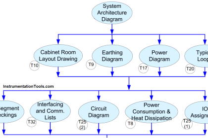
In this article, we discuss the topic on different parts of DCS system layout and its modules like processors & IO cards, marshalling & system cabinets, engineering & operator workstations, and Switch.
Distributed Control Systems (DCS) plays a vital role in manufacturing, production industries as they are used to control and manage the processes.

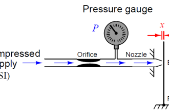
Image Courtesy: manufacturingchemist
Distributed Control Systems are extension of traditional controllers. The major concept of distributed control systems application is derived from the idea of decentralizing the control unit and establishing a common network between the operator, engineering stations.
DCS tends to be used on large continuous process plants where high reliability and security is important, and the control room is not geographically remote.
DCSs are connected to sensors and actuators and use set point control to control the flow of material through the plant.
Read: DCS Tutorial
Although 4–20 mA has been the main field signalling standard, modern DCS systems can also support field bus digital protocols, such as Foundation Fieldbus, profibus, HART, Modbus, PC Link, etc., and other digital communication protocols such as modbus.
DCS System Layout

DCS System – Level 0
This level contains the field devices such as flow and temperature sensors, and final control elements, such as control valves.
DCS System – Level 1
This level contains the marshalling cabinets where the field termination takes place. Also houses the intrinsic safety barriers, relays, Terminal blocks, Isolators etc. from here the signal travels from the Junction boxes wherein the signals are paired and received from the appropriate sections in the field area.
DCS System – Level 2
This level contains the system cabinet which is designed to accormodate power supply,controller and I/O cards. The field signals will be digitally processed by the I/o cards and sent to the controller for further digital processing.
This part will be located in the top most part of the cabint and will be brain of the automatic system.
DCS System – Level 3
This level consists of visual disply unit or computer, is the operator interface. It is production control level, which directly control the process. Plant operational schematics are displayed. Alarm and interlock cause and effect diagrams are displayed in different pages.
Read: Types of System Architecture
System Cabinets
In system cabinet, all electronic modules will be installed like processor cards (CPU), input modules, output modules, serial communication cards, power supply modules, rack to rack inter-communiacation modules, fieldbus cards, profibus cards, modbus cards.

Main types of input modules are analog input (AI) cards, digital input (DI) cards. The number of IO channels will vary depends on the user selection of these cards like 8 channel, 12 channel, 16 channel & 32 channel.
Similarly output modules are analog output (AO) cards, digital output (DO) cards.
Marshalling Cabinets
Marshalling cabinets shall be used to terminate all field cables as well as for grouping of various signals from the field devices properly tagged.

Sometimes different marshalling cabinets can be allocated based on type of signals like analog input/output signals, digital inputs, digital output and relays.
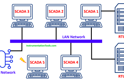
Operator WorkStation
The operator workstations are used for monitoring all system operations and for effecting control actions and parameter adjustments.
There are normally multiple operator workstations, as illustrated in above figure, each of which contains all of the process graphic displays and historical trend displays for the system.
Some of the operations performed through the Operator workstations are listed below;
- Logging on and off the system using passwords and user names
- Invoking process displays to view the operations throughout the system
- Effecting control modes for various equipment in the system; for example, Manual and Automatic modes, placing equipment in or out of service
- Changing setpoint parameters, with appropriate security allowance
- Effecting manual control actions for equipment, such as start/stop and open/close
- Viewing historical trend displays and transferring data to other files for exporting
- Viewing the current alarm summary to identify alarm conditions requiring attention.
- Viewing the alarm/event summary to view the chronological series of events.

Fig: DCS TDC2000 operator workstation (old model)
Engineering WorkStation
- To build graphics using the graphic builder programme.
- The configure control loops/monitoring loops
- To assign I/Os to various I/O modules during generation of application software.
- To configure shutdown logic/sequence logic.
- To write/edit user written program in higher level languages.
- To download the generated application software to various system nodes. To generate “self documentation” i.e. it should be possible to store the generated information on a CD as well as to enable user to take a printout of the system configuration.
- To emulate generated control loops/scheme/graphics, etc. before it is downloaded to any control processor or operator stations.
- The graphic and database equalization of all the operator station shall be performed from engineering station with a single command. It should not require manual copy/paste intervention by user.
Switch
A switch is a intelligent device on network. A switch is a device in a computer network that connects other devices together. Multiple data cables are plugged into a switch to enable communication between different networked devices.

Switches manage the flow of data across a network by transmitting a received network packet only to the one or more devices for which the packet is intended.
Each networked device connected to a switch can be identified by its network address, allowing the switch to direct the flow of traffic maximizing the security and efficiency of the network.
Communication Media and Protocols
Communication media consists of transmission cable to transmitt the data such as coaxial cables, copper wires, fiber optic cables and sometimes it might be wireless.
Communication protocols selected depends on the number of devices to be connected to this network.
In DCS, two or more communication protocols are used in between two or more areas such as between field control devices and distributed controllers and other one between distributed controllers and supervisory control stations such as operating and engineering stations.
Reference: Wikipedia
Read Next:
- Industrial Control Systems
- Industrial Automation Systems
- Documentation of PLC & DCS
- Project Planning DCS System
- Functions and Parts of PLC
- Remote Functions in Systems


https://instrumentationtools.com/dcs-system-layout/
DCS System – Level 2
accormodate- wrong spelling?
cabint – wrong spelling
Engineering WorkStation
the configure to to configure