Operator interface or human-machine interface (HMI) for SCADA systems provide the functions of status indication, alarm reporting, operator intervention in control action, and data storage and programming.
Operator Interface

Several levels or layers of operator interfaces are required to provide a reliable and maintainable system: equipment level, controller level, and supervisory level. At the controller and supervisory level, HMI may also provide the capability to modify the controller program.
Note: The below-discussed points may vary from industry to industry. Consider the below example for understanding the basics. Real-time applications may vary as per specific industry standards.
Equipment Level
Equipment level HMI should consist of a minimum of the control switches and indicators necessary to permit an operator to manually control the equipment in the absence of communications from the controller or for maintenance purposes.
Examples of this level of control are hand-auto-off switches and indicator lights at motor starters; local-remote switches, potentiometers, and meters at variable frequency drives; and circuit breaker control switches, meters and indicator lights at switchgear.
The table lists minimum manual control capabilities to be provided for mechanical and electrical system components.

Table 1. Minimum manual control capability
Manual control substitutes the industrial facility operator for the automatic control system in the feedback loop and leads to the risk of system or equipment misoperation due to human error.
Safety interlocks, such as motor overload, high-high pressure switches, fire detection, etc. should, therefore, be hard-wired into the control circuit such that they are active in both manual and automatic control modes.
Switchgear protective relaying required for fault protection should always be hard-wired in the circuit breaker trip circuit and not dependent upon the controller.
In some cases, hard-wired manual controls for entire industrial facilities have been centrally located in a control panel or bench board at the control room.
Although this simplifies operator intervention upon complete failure of the automatic control system, it is not recommended as the lack of physical segregation compromises reliability. A catastrophic structural or environmental failure at the control room would disable both automatic and manual control capability.
Controller Level HMI
At the controller level, the primary HMI device should be a graphical display/keypad combination providing access to input and output data, timer and register settings, and alarm and status screens.
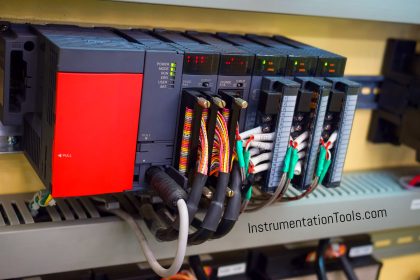
These devices are commonly panel-mounted in the door of the PLC cabinet and are available in enclosures suitable for hostile environments.
With password-protected access control, the controller level HMI may also provide a means of accessing and modifying the controller program logic. The below table lists the minimum recommended functionality of controller level HMI.

Table 2. Required controller level HMI functionality
Note (1) Increasing numbers indicate more restricted levels of operator access. Access levels are typically password-protected. Each access level includes the functionality of those below it.
Supervisory Level HMI
Supervisory level HMI devices are typically personal computer workstations located in the central control room and/or management and engineering offices. The quantity and function of these workstations depend on the size and complexity of the industrial facility.
Simple industrial facilities may be provided with a single workstation, which may be located in the main electrical or mechanical space in the absence of a central control room.
Large or complex industrial facilities should be provided with a minimum of two workstations in the control room to permit operators to back one another up, plus the additional workstations required for engineering use, management overview, or data storage and reporting, as determined by the industrial facility manager.
Multiple-building campuses should be provided with workstations in the mechanical/electrical space of each major building to permit operations staff to obtain status and alarm information for the entire industrial facility from any building.
Graphical Screens
Supervisory level HMI uses graphical screens displayed on the computer monitor to communicate system status and alarm conditions.
Screens should be configured for industrial facility overview, system overview, subsystem, and equipment screens for all major components of the industrial facility.
Remote manual control and supervisory control is typically performed at the supervisory level HMI under security access control.
Trend Data
Trending and data storage capability should be included in all SCADA systems to provide a permanent log of industrial facility performance. All critical system parameters, such as temperature, humidity, voltage, current, should be stored every 1 second or 1 minute as per requirement. (or other specified preset time intervals).
The system should have the capability to record critical signal values more frequently at an operator-selected rate when prompted from the HMI or by a signal from operating equipment. The system should automatically return to its primary trending when system operation returns to normal.
Data storage should utilize a separate server or drive from that used for the primary system control software and should be periodically backed up. Records should be maintained on-site for a minimum of 5 years (or as per industry standard).
Human factors
The design of HMI for SCADA systems must include consideration of Human Factors Engineering (HFE). It is estimated that 50 percent or more of all loss of load events in mission-critical industrial facilities involve human action.
A commonly reported scenario begins with a single component failure and correct response by the automatic control system to isolate the failure and maintain service to the load, however resulting in an off-normal system condition.
Incorrect human intervention in attempting to restore the system to normal conditions then results in loss of service to the load. Consideration of HFE in the layout of operator controls can help prevent these occurrences.
Labeling
Labeling: All control devices must be clearly labeled with letters that are large enough and provide high contrast with the background to be clearly legible in a hurry at a full arms length.
The primary designation should be the functional description of the device, ex: “Generator No. 1 Speed Control”. The label should also carry the tag number of the device, ex: “43GS-1” that corresponds to the system documentation, but this information is secondary in emphasis and size to the primary designation.
Layout
Controls should be arranged and grouped in an intuitive and logical manner. Some of the many techniques that may be used to design intuitive layouts include:
- Grouping controls associated with individual pieces of equipment such as a chiller or a generator with substantial separation between groups.
- Placing control switches left-to-right, or top-to-bottom in the sequential order in which they are operated during a normal startup or shutdown.
- Spacing devices far enough apart so that labels are clearly associated with their device and an operator’s hand does not obscure the labels on adjacent devices.
- Arranging controls in the physical or electrical order of the process, using a mimic diagram or mimic bus.
- Color-coding control devices by function; ex: green start buttons, red stop buttons, yellow lamp test buttons, etc.
- Colored backgrounds or borders to emphasize grouping of controls on large control panels.
Color Schemes in SCADA
Color schemes used for controls and for graphic screens may duplicate color codings used within the process, such as piping color codes or system color codes, or maybe developed strictly for the HMI.
In all cases, colors should be selected to provide high levels of contrast without eye fatigue. Some rules for the use of color in HMI displays are given in table 3.

Table 3. Rules for HMI colors schemes
Select-before-operate:
HMI software should be programmed such that an operator must select the device to be controlled by point-and-click or other means and then select the operation to be performed.
This two-step requirement for manual control can reduce errors resulting from the selection of the incorrect device. The selection of a device to be controlled should result in highlighting that device on the screen, providing the operator with a visual verification of correct selection.

Table 6. RGB values for standard colors
Reference: This material adapted from the “Department of the Army, TM 5-601, Supervisory Control and Data Acquisition (SCADA) Systems for Command, Control, Communications, Computer, Intelligence, Surveillance, and Reconnaissance (C4ISR) Facilities, 21 January 2006.”
If you liked this article, then please subscribe to our YouTube Channel for PLC and SCADA video tutorials.
You can also follow us on Facebook and Twitter to receive daily updates.
Read Next:
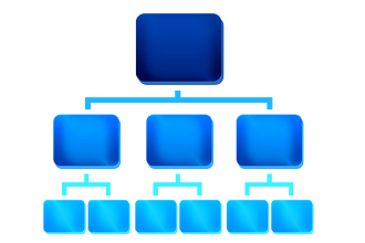
- Architecture of Instrumentation
- What is PID Controller?
- Concept of Latching in PLC
- Alarm Management Practices
- Examples of SCADA and PLC


Very nice, I like SCADA, HOW can I get a handbook scada for a power plant power station
I would like to learn PLC, SCADA and general power automation…. Any advice