For FF Cable installation one must ensure:
To maintain the Isolation and Integrity of the FF Signal wiring.
- Maintain the Shield integrity up to the termination points. For both multi-pair and single pair of FF cables.
- Maintain the integrity of multi-pair cable shields both Overall and Individual
FF Cable Installation
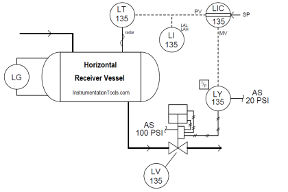
Typical FF Installation is shown below:
FF Architecture Basics
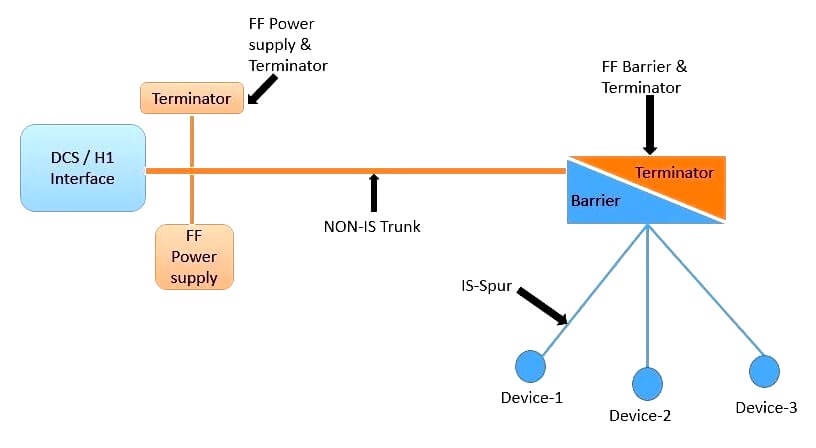
FF Wiring Basics
Also Read: Foundation Fieldbus Theory
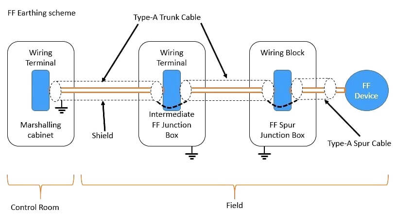
FF Earthing
Cable type: Recommended Type A cable Shielded twisted pair
Other cable is possible, but there are limitations in terms of achievable cable distance and electromagnetic compatibility (EMC).
Fieldbus is a digital “high speed” (31 kBit/s) communication, a current modulated signal superimposed on the DC power.
Two Types of Cable Installation
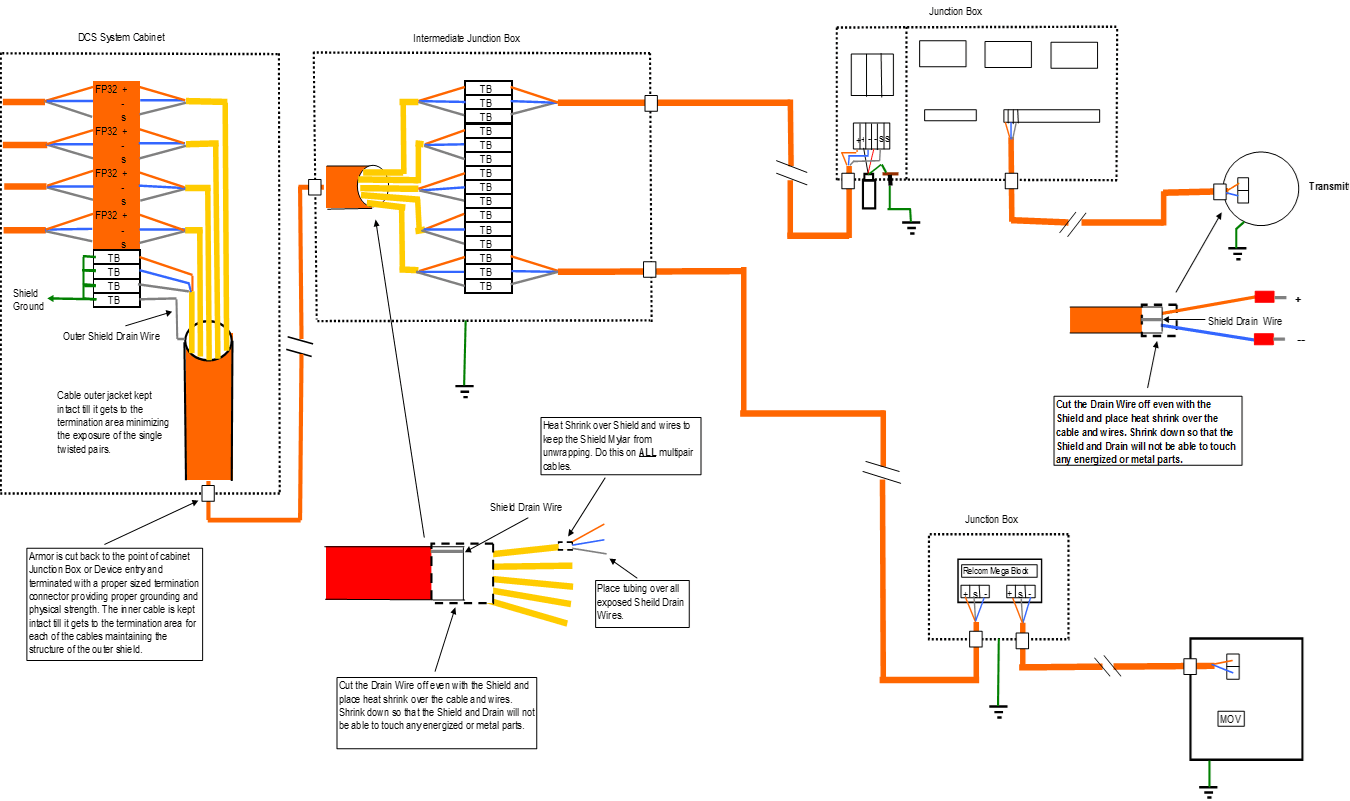
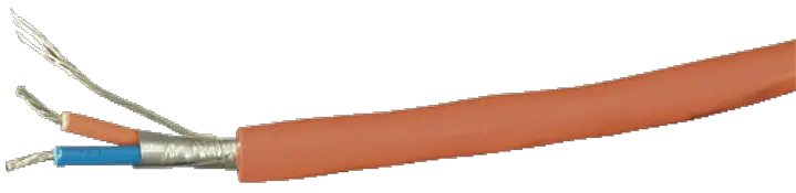
Single Pair Cable
Shielded Twisted Pair with Double Shield and Single Drain.
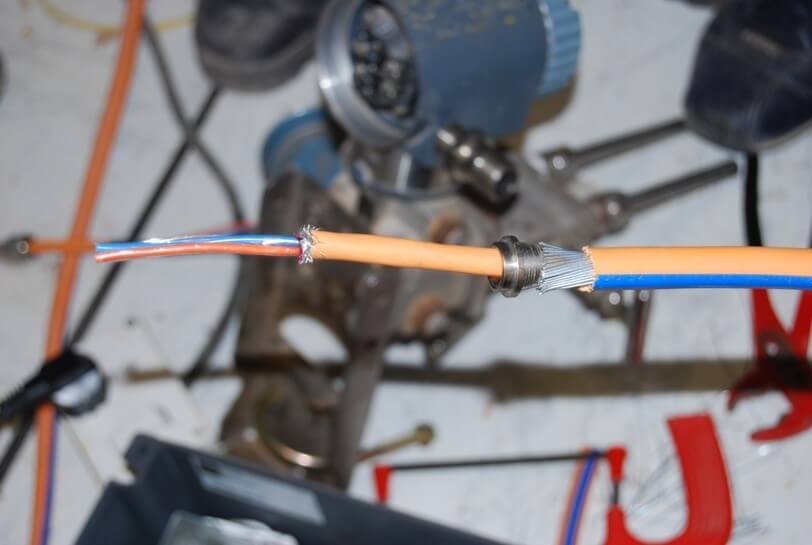
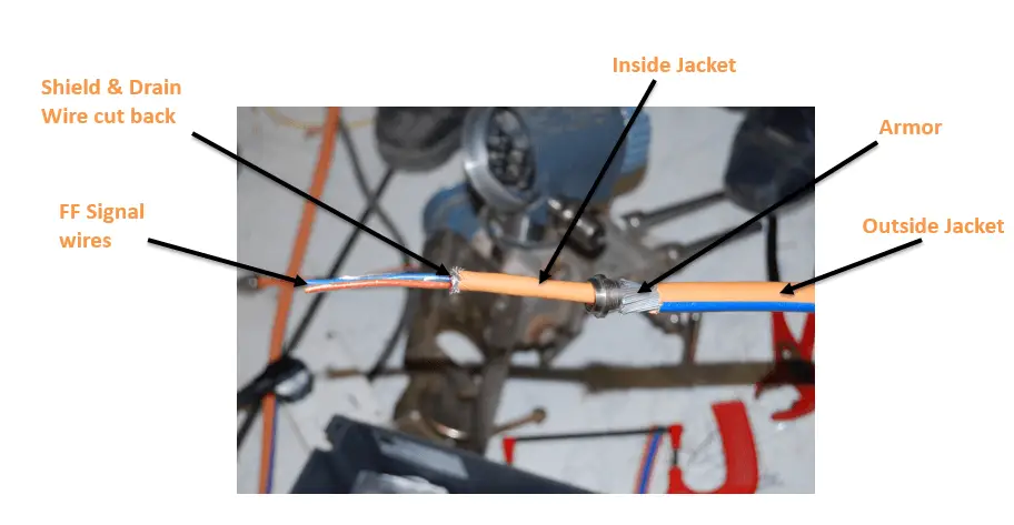
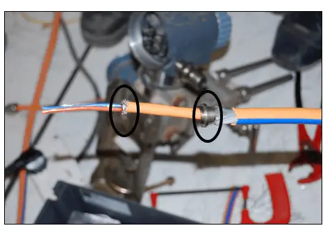
Areas which needs to monitor and requires closer attention are encircled below:
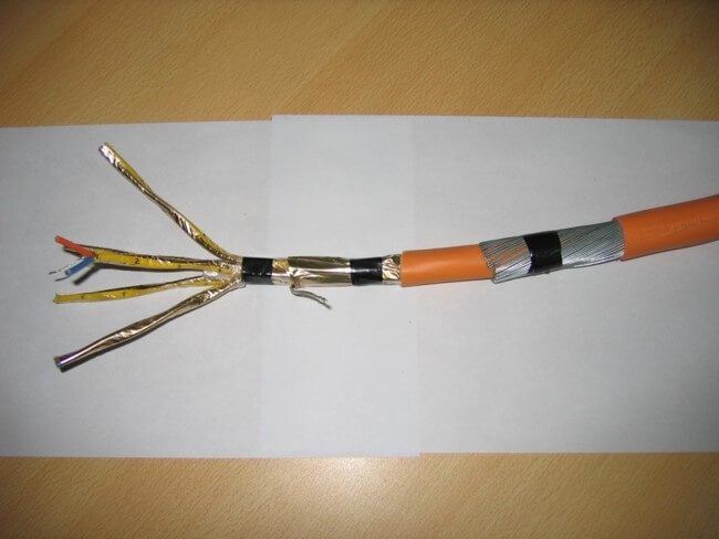
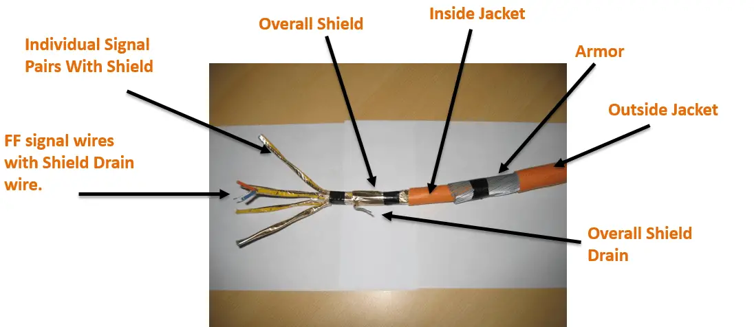
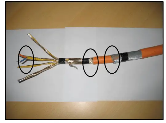
Multi-Pair Armored
Shielded Twisted Pairs with individual Shield Drains and one overall Shield with Drain.
Areas which needs to monitor and requires closer attention are encircled below:
Proper installation of the Fieldbus Foundation (FF) system cable will minimize any start-up and long term operational issues.
- FF is a communications system not a 4-20 ma signal loop.
- FF is an AC signal and impedance issues do cause signal degradation and possible operational issues.
- Better than 90% of FF system installation issues are found with the cabling and segment installation.
- The proper tools and procedures are needed to minimize installation issues.
FF Cable Preparation
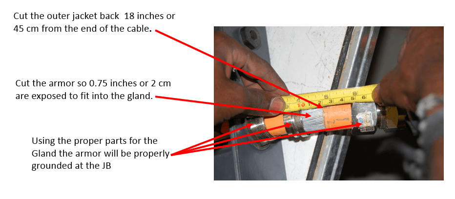
During the preparation of the FF cable care needs to be taken while cutting the Jackets and any of the Insulation or Shielding to make sure that there is no damage is caused to the lower levels:
- When removing the outer jacket and armor do not cut or nick the inner jacket.
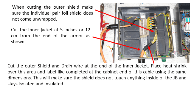
- When removing the inner jacket make sure you do not cut or nick the Shield Mylar or Drain wire under the inner jacket.
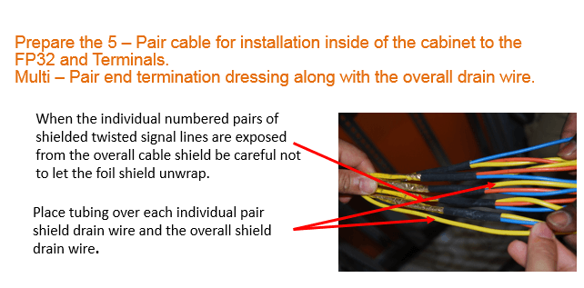
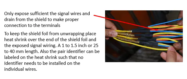
- Make sure to keep the individual pair Shield Mylar and Drain wire intact until it is secured so it does not unwrap and expose the signal wires of the individual pair or pairs.
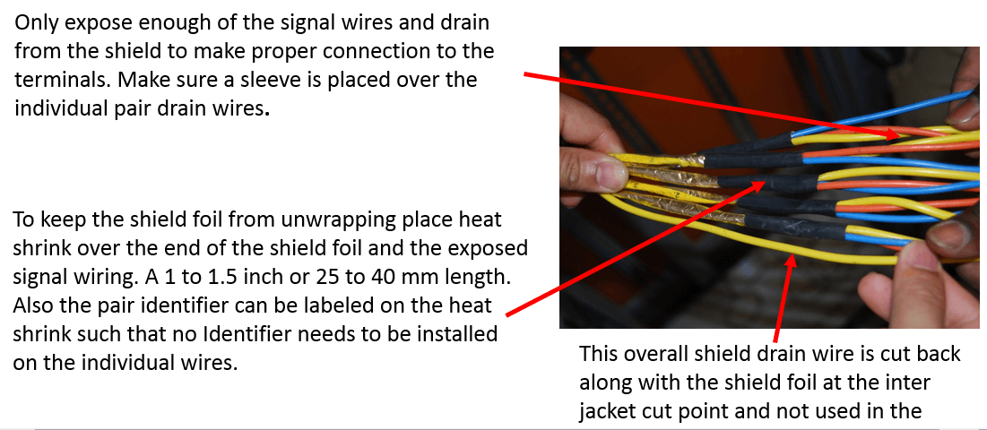
- Minimize the amount of exposed signal wire.
- Make sure all of the Shield and Drain wire areas are trimmed back at the instrument ends prior to securing with Heat Shrink.
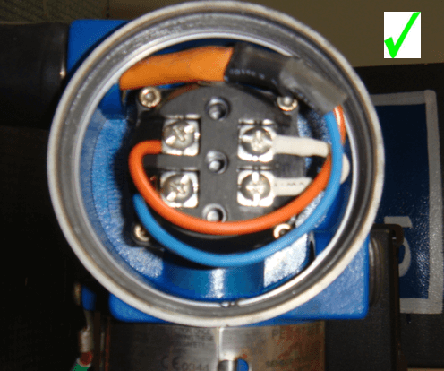
Transmitter Termination
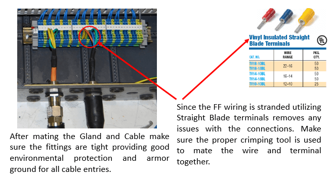
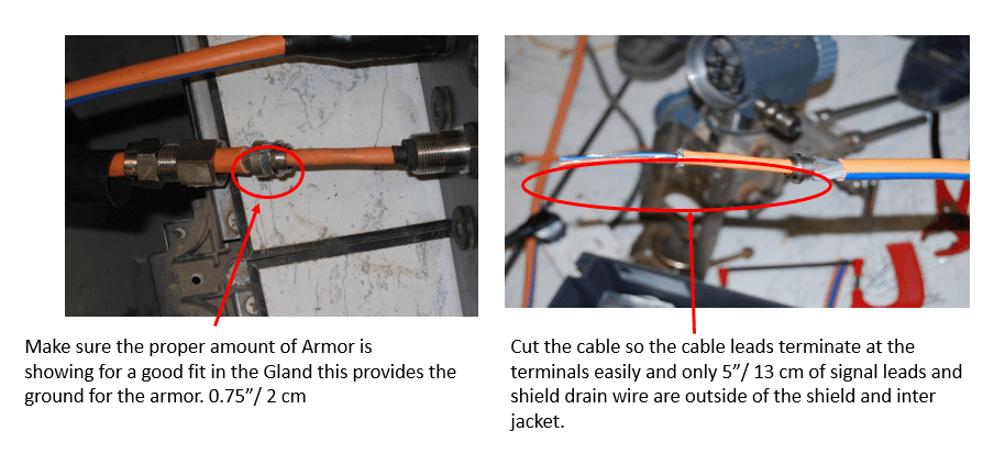
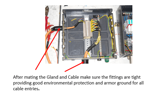
Prepare the instrument cable for proper gland installation and grounding. Leave a reasonable amount of inside jacket protection the cable through the instrument case.
Cut the cable so the signal wires are long enough to proper dress out and connect to the instrument signal terminals.
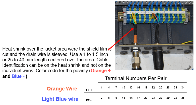
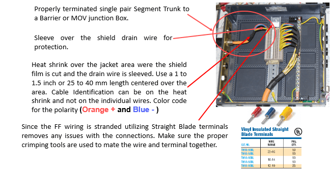
Heat shrink over the jacket area were the shield film and drain wire is cut and sleeved. Use a 1 to 1.5 inch or 25 to 40 mm length centered over the area.
This is to make sure the Shield and Drain wire do not touch the case and is isolated at this end. Cable Identification can be on the heat shrink and not on the individual wires.
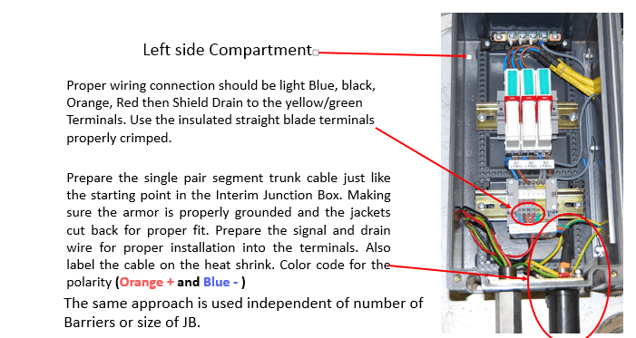
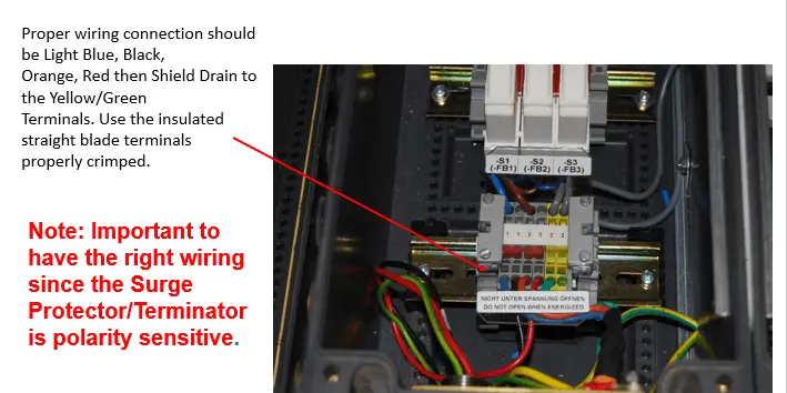
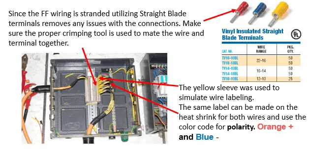
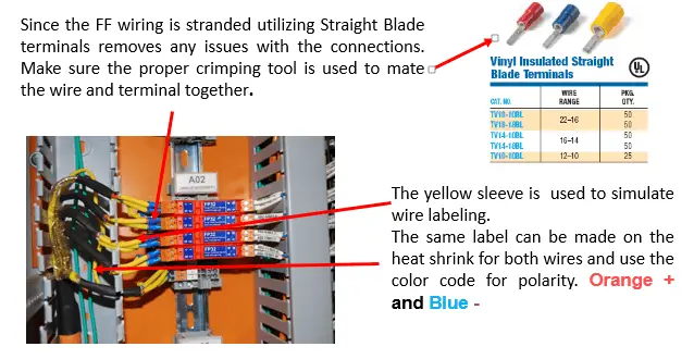
Properly terminate the instrument. The yellow sleeve is to represent individual wire identification which is not needed if the heat shrink sleeve has the cable identification on it. Use standard wire polarity identification color code for the polarity (Orange + and Blue -).
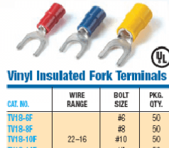
Since the FF wiring is stranded utilizing Insulated Fork terminals removes any issues with the connections. Make sure the proper crimping tool is used to mate the wire and terminal together.
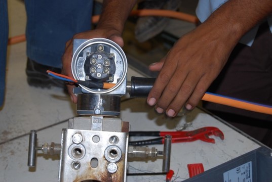
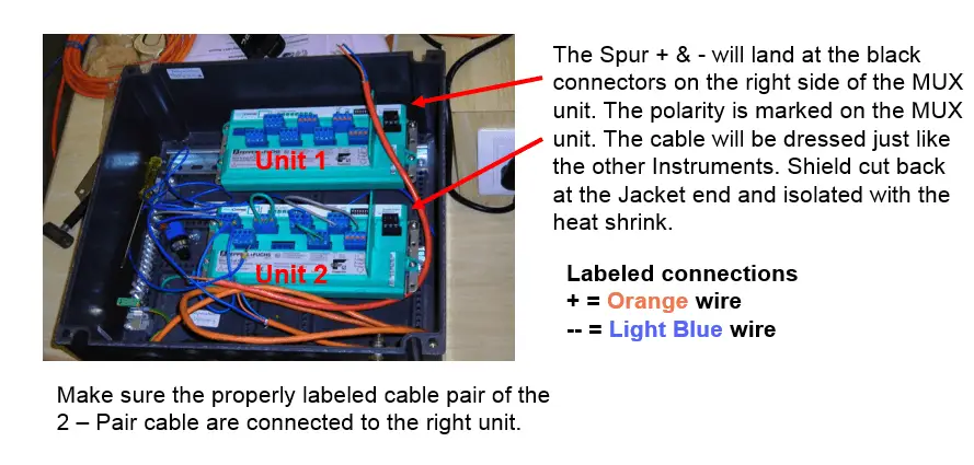
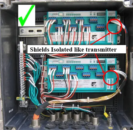
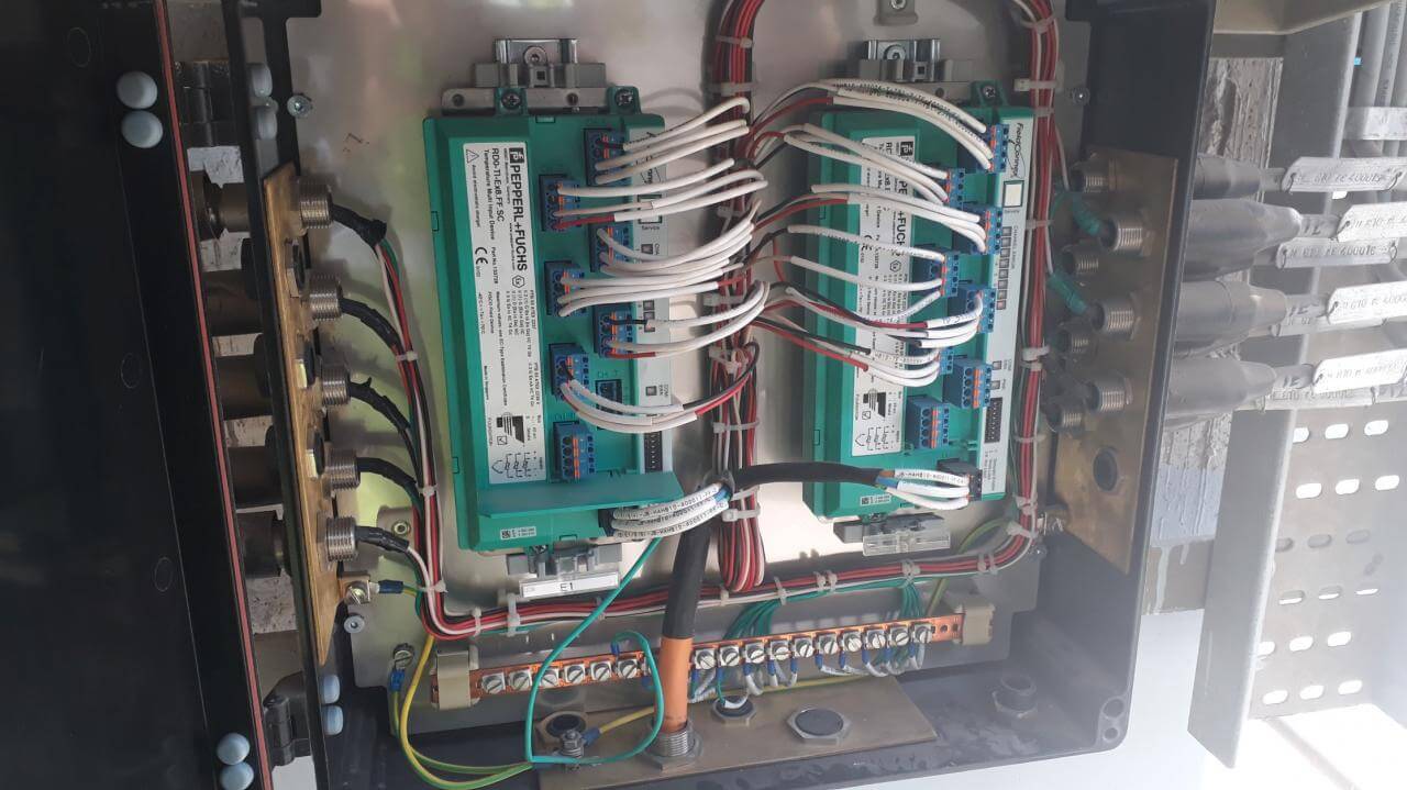
MUX Junction Box Termination
This is a representation of the Junction Box for the P+F MUX transmitters. The same cable preparation and installation is used as the other JB’s.
Use the proper armor termination in the gland the difference is a 2 – Pair cable is being used.
An M25 cable gland will need to be used with the M20 gland for this 2 – Pair cable in both JB’s.
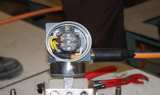
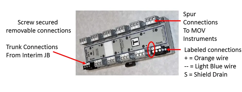
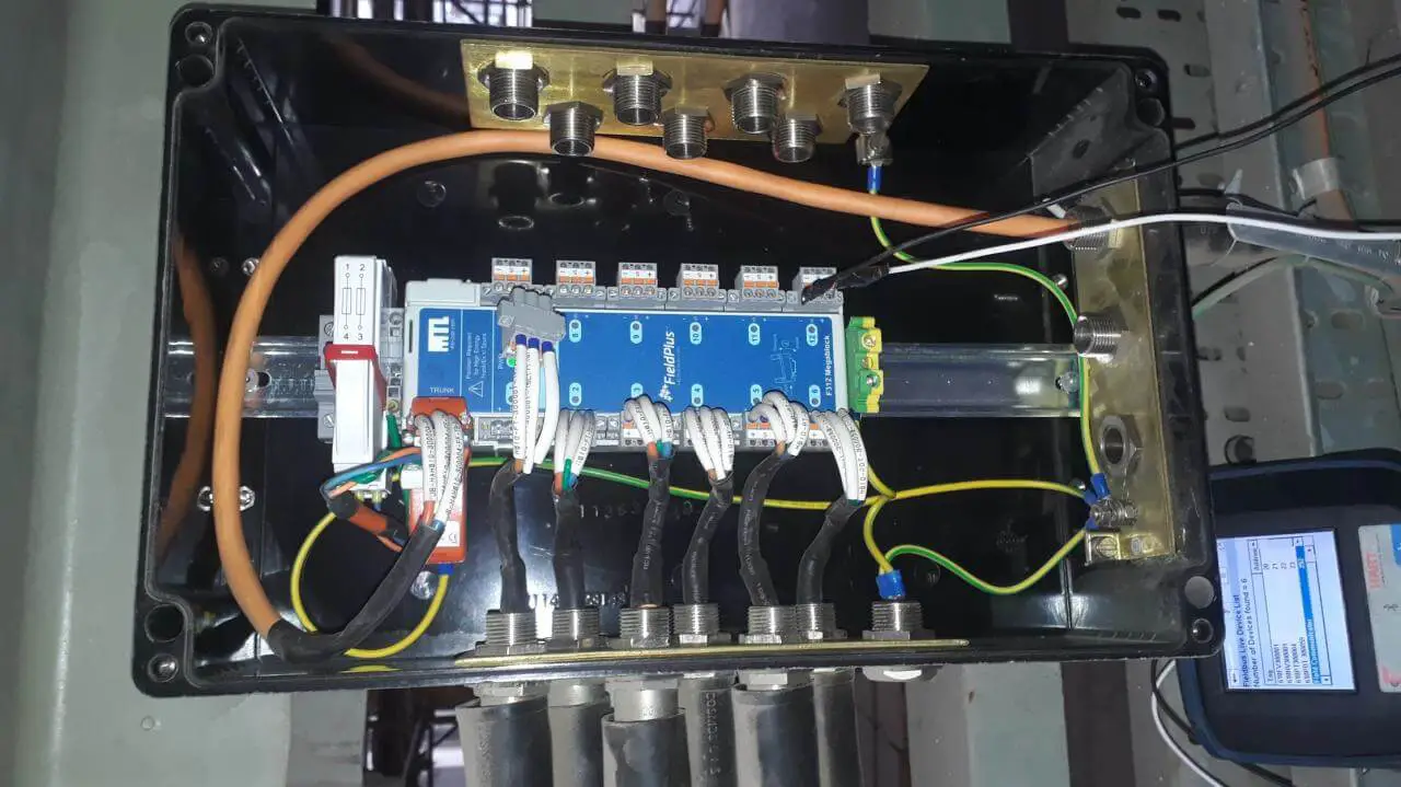
MOV Junction Box
This JB uses the same cable input/output as the Barrier JB so the preparation of the cable and gland system is the same.
The difference are:
- Trunk input connects to a input terminal block similar to the Barrier JB.
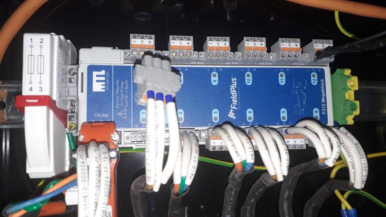
- The Spur’s are connected directly to the Relcom Mega Block.
- The Relcom Mega Block has labeled pluggable connectors the cable is terminated at.
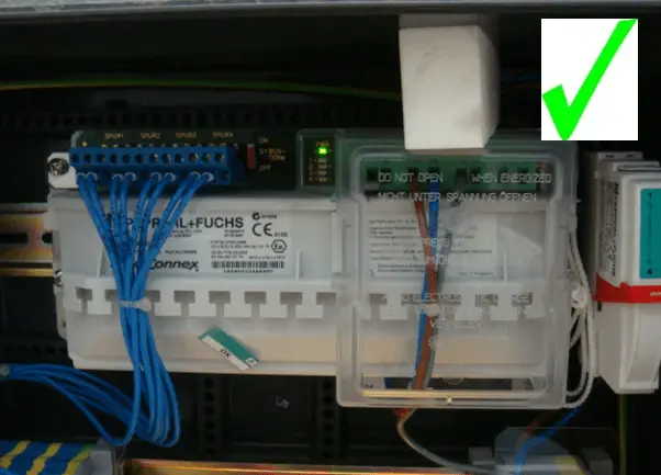
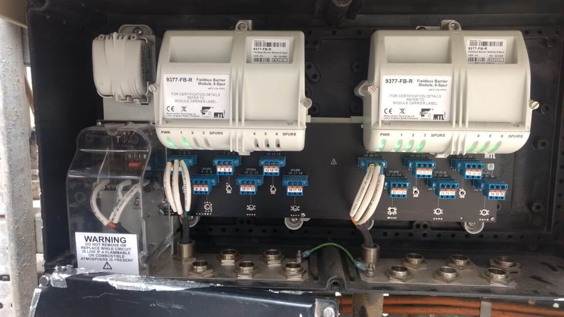
Barrier Junction Box Spur Output
12 way Fieldbus Barrier Enclosure
Each Spur has two blue and a yellow/green terminals associated with it.
Starting from the left terminal, the terminations start to corresponds with the left Barrier and its four Spur outputs then continues over to the next Barrier.
See the table below for the polarity and pairing.
FF Barrier Junction Box
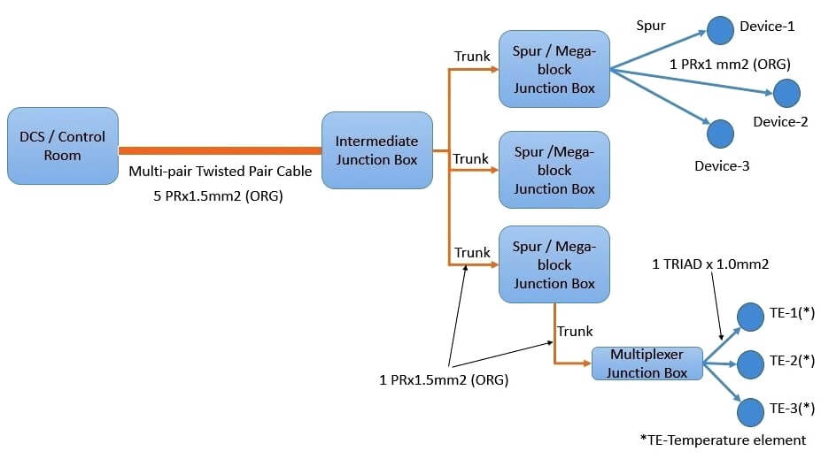
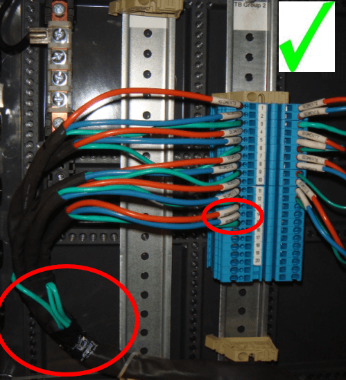
Intermediate Junction Box
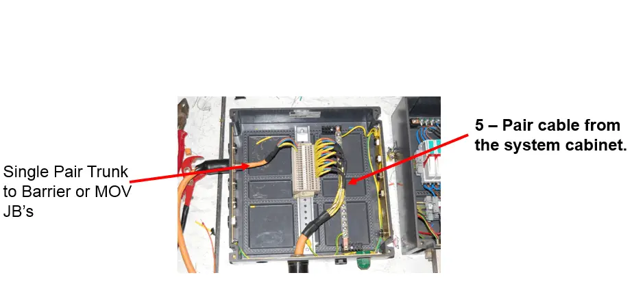
The Interim Junction Box is used to terminate the 5 – Pair cable coming from the Invensys cabinet to the process area.
From this point the individual segments, a single FF pair cable are used to continue to the Barrier or MOV Junction Boxes for that Process area.
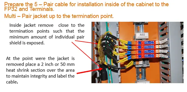
Preparing the 5 Pair cable for mounting in the Interim Junction Box
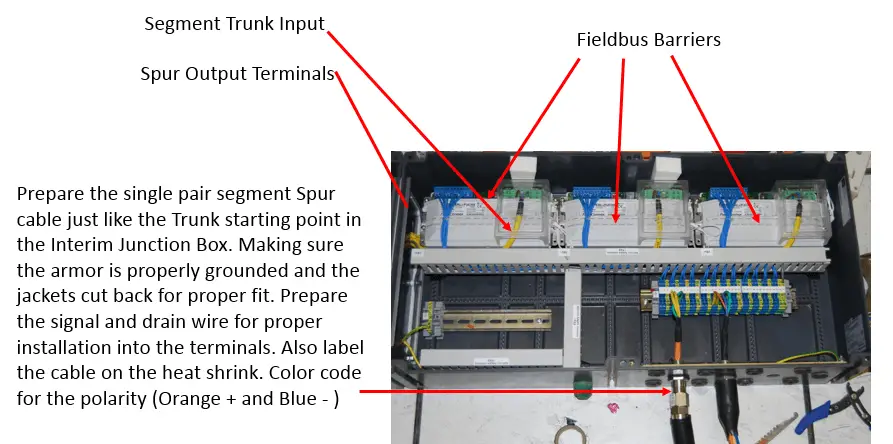
Preparing the Single Pair cable for Terminating in the Interim Junction Box
Prepare the single-pair cable for mounting in the Junction Box by striping the outer jack back to a point allowing proper intrusion into the box for termination.
Preparing the 5 – Pair cable for Terminating in the Interim Junction Box
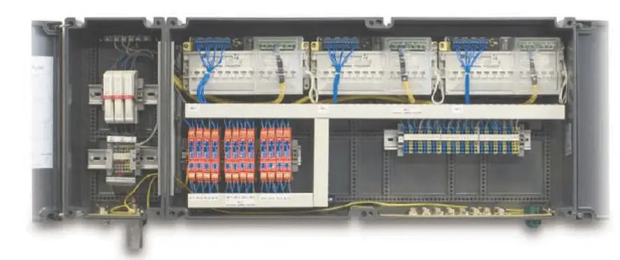
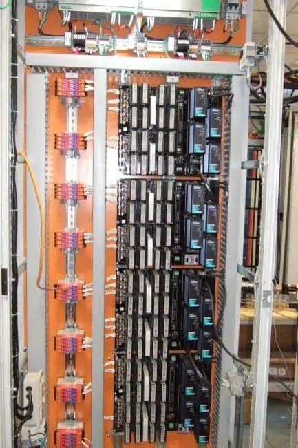
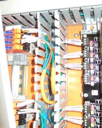
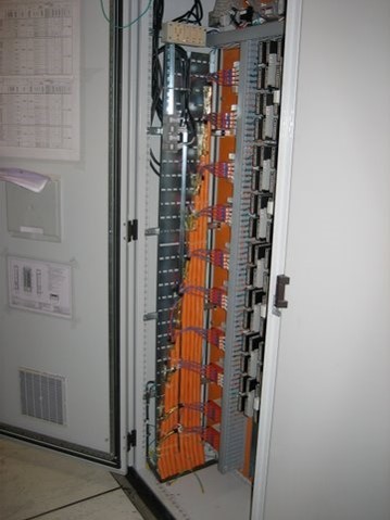
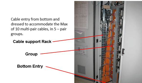
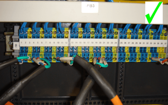
FF Marshaling Panel
Points to ponder:
Foundation Fieldbus Do’s
- Proper Inspection of cables and equipment.
- Standard tools to be used.
- Proper cable laying and shielding to be carried out.
- Standard mounting for Junction Box.
- Proper cabinet wiring (no crosstalk)
- Proper cabinet installation is essential, and so is the wiring from the control room to the field.
Foundation Fieldbus Don’ts
- FF cable not be laid along with cables carrying electrical signal.
- Non standard lugs and tools not be used.
- Ensure that cable length of one segment is not more than 1900 meters.
FF Physical layer checks
Check the overall shield of 5 pair cable should be connected at instrument earth.
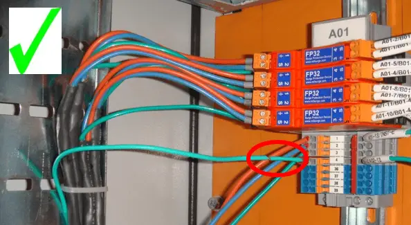
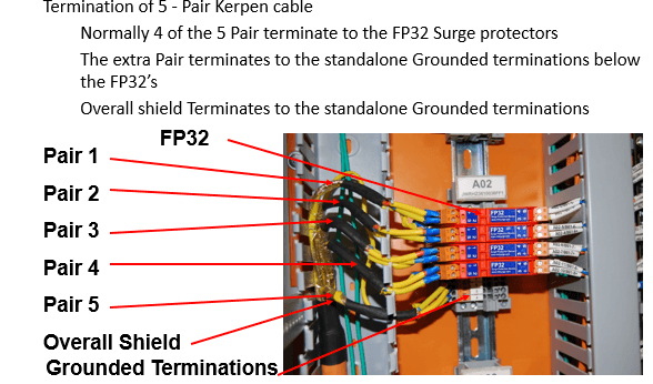
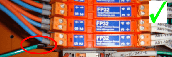
Check individual segment shield should be connected to FP-32 shield terminal
Check the overall shield of 5 pair cable should not connect in IJB and insulated properly. Spare cable (5 Pair) to be terminated in spare TB’s.
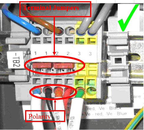
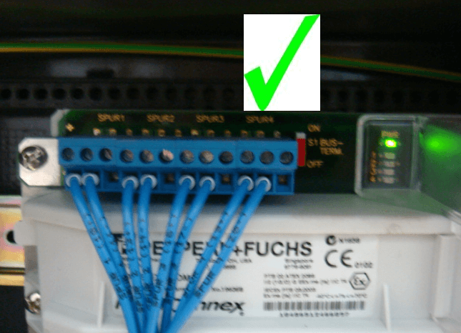
Open Spur JB and check for the input terminal jumpers on the FF trunk side are set and locked into the terminal. and also check TP32 terminator connection and polarity with H1 segment.
A. TP-32 Terminator Polarity
Red: Positive & Black: Negative
B. Segment Polarity
Orange: Positive & Blue: Negative
Check loop connections at isolation switch.
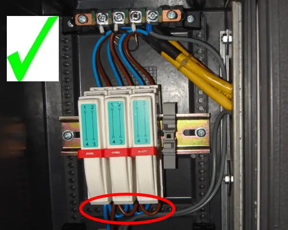
TP-32 terminator earth cable should be connected with Plant Earth (JB earth)
Check power LED of Barrier is ON and no fault LED will Glow .
Measure voltage at spur is above 11 V DC.
Make sure all barrier terminator switches are in the off position
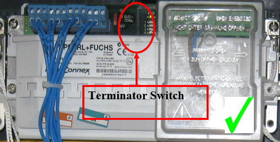
In case if the standard TP-32 terminator are not available one of the barrier terminators can be activated.
First turn off the terminator switch of the barrier then install the TP-32 terminator.
Open the cover and check the segment connection at barrier end and also check the Device connection at spur end.
Check connections at Field cables.
Shield cable should not be connected at Device end.
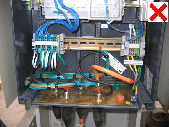
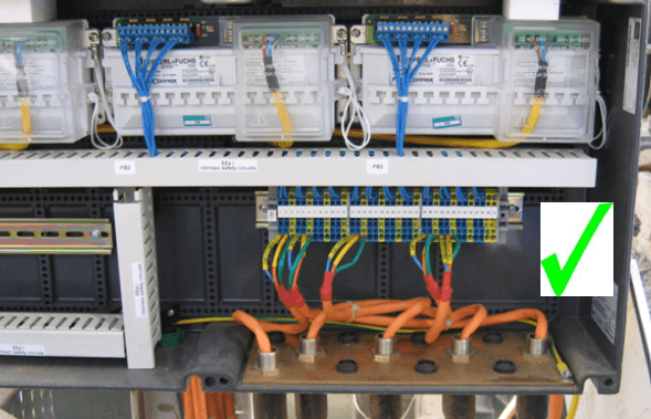
In the Mux JB boxes make sure both the outside and individual twisted pair shields are cut and isolated from the metallic part in the box.
Do not use wire to tie-down cables it cuts into the insulation allowing liquid egress. Use wide nylon or steel strap cable ties.
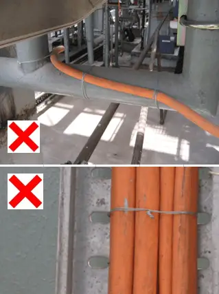
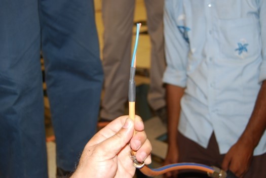
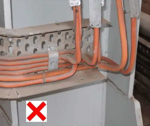
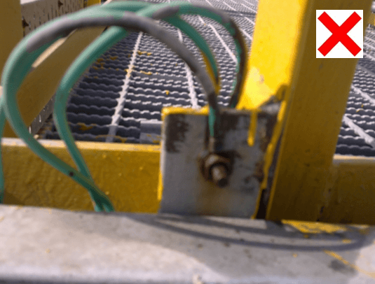
Maintain the shield foil up to the termination point. Keep the leads as short as possible.
Photo graphs shows Spur and Extend Trunk signal wire not Shielded and too much of the signal exposed, so below arrangement is not acceptable.
Monitor the cable bends and make sure they are not tighter than 10x the diameter of the cable or bending should be greater then 110° bend radius or less then 70° bend radius.
Please do not bend FF cables beyond 90 Deg and don’t use wires as a tie to hold cables instead use wide nylon, steel or aluminum strap cable ties.
90 deg bend for FF cable
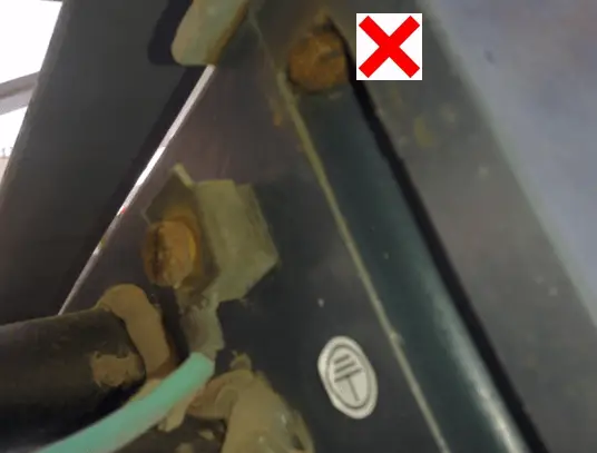
Check for corrosion inside the JB and outside earthing connections and also check for earthing points that are not covered with paints.
Corrosion is enemy for signal
Painting Too much
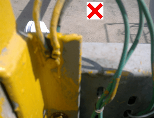
Un healthy earth connection corrosion
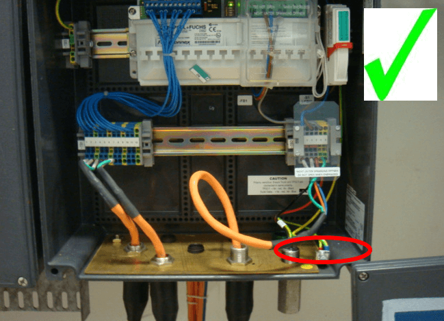
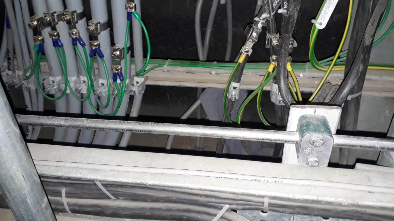
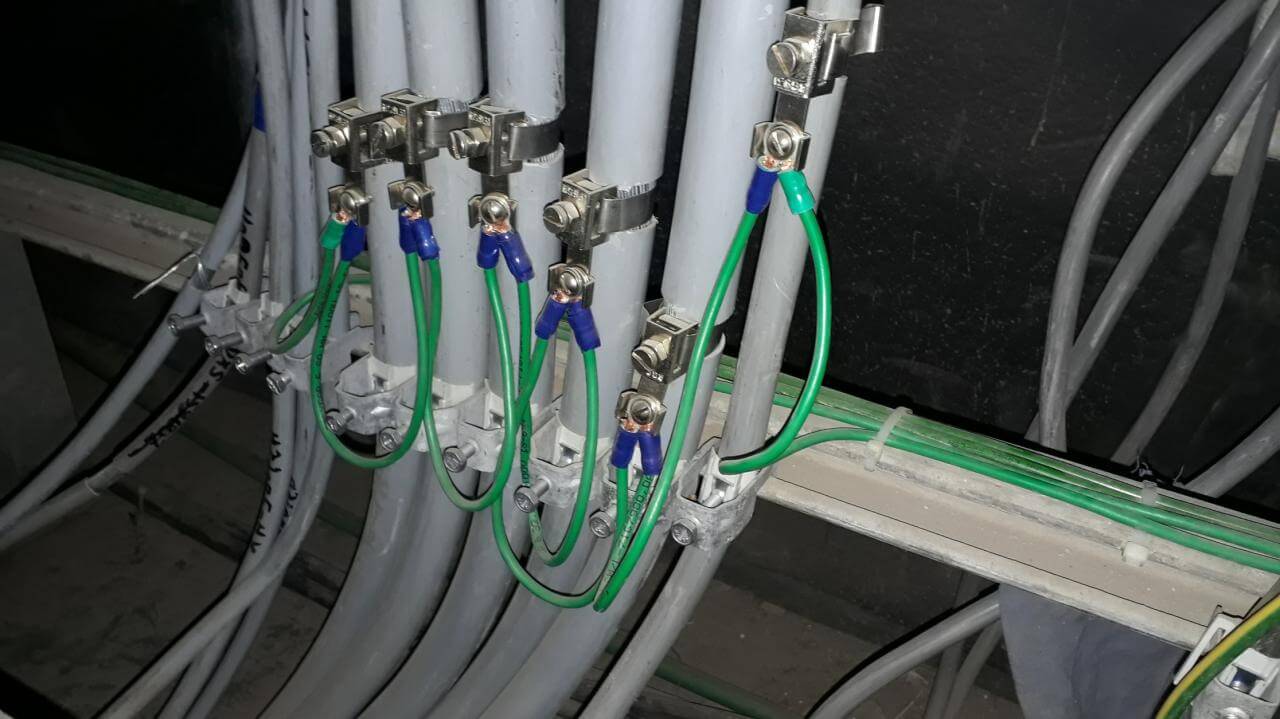
FF Devices are having ground points connected to instrumentation cable trays, these cable trays are welded with each other and connected to plant earth grids.
The FF device earthing is important for devices to function properly during surge/lightning / any fault current.
It is observed that many places due to new addition / modification/ rusting, cable trays are disconnected with each other.
Cable tray welding joints also corrode with time and the electrical resistance of the cable tray increases which deteriorates earthing effectiveness.
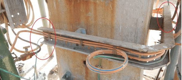
Attached snap of instrumentation cable tray, which are not connected with other tray nor grounded, but sensitive FF devices grounds points are terminated in tray. So sensitive FF devices are not connected to earth and vulnerable to earth fault related issues.
It is recommended to connect FF devices earth points directly to plant earth grids instrumentation risers instead of Instrumentation cable trays.
Care should be taken to land (earth) spare trunk pairs on terminals in order to avoid possible noise interference at PIB end. Regularly monitor various FF physical parameters like FF,HF & LF noises, retransmissions, jitters, voltage levels, error codes from devices, Live lists, waveforms using oscilloscopes.
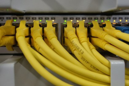
One of the important finding is don’t run any other cables in FF trays such as 230VAC/440VAC power supply or PA system cables or any high voltage/current cables as it may produce noise in FF system. Which reduces reliability of the system.
Prevent water seepage in FF JBs which creates corrosion in active electronics components and degrades segment performances.
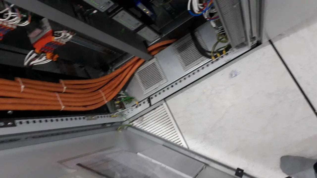
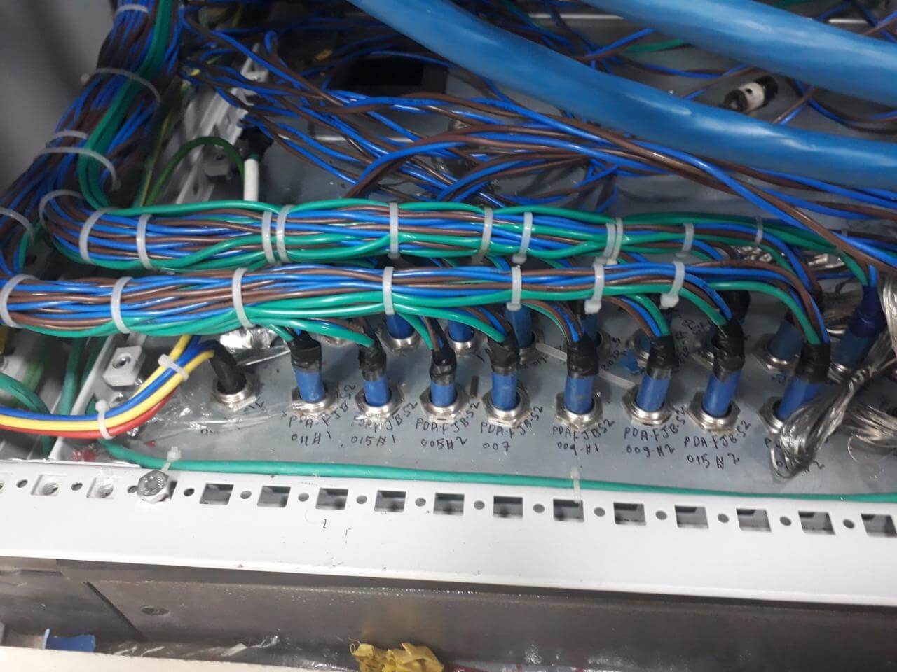
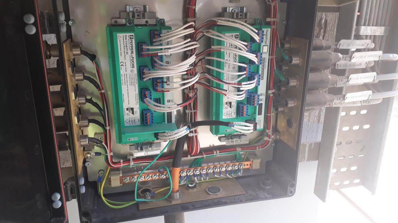
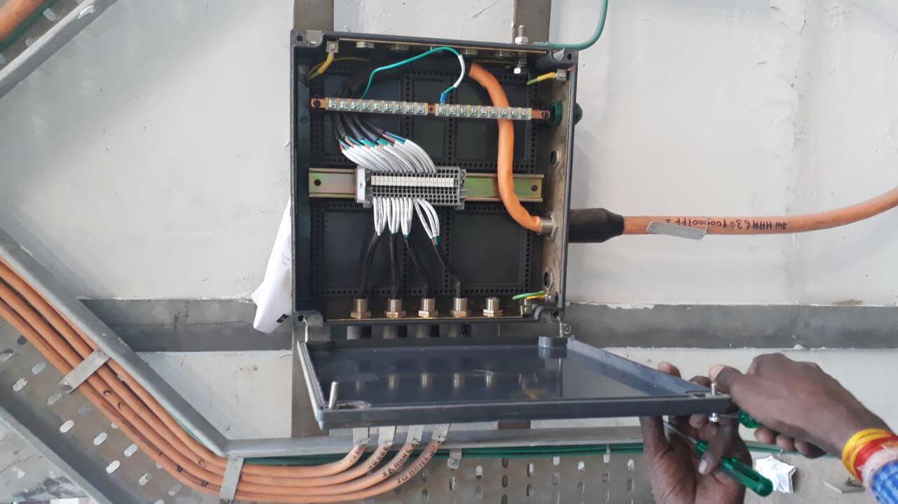
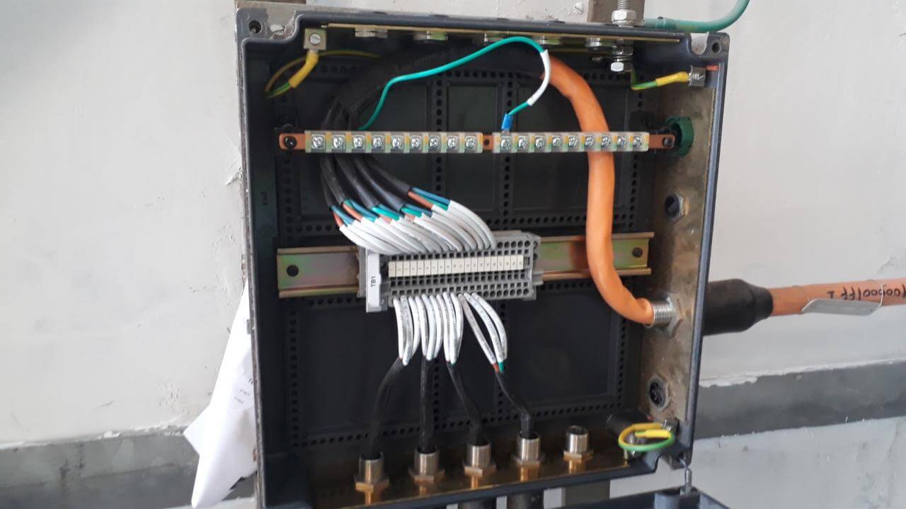
Foundation Fieldbus Pictures
Enclosed herewith some pictures from actual onsite Fieldbus Junction Box and Panel side cable terminations.
Marshalling cabinet End Termination. Type-1 FF Cable
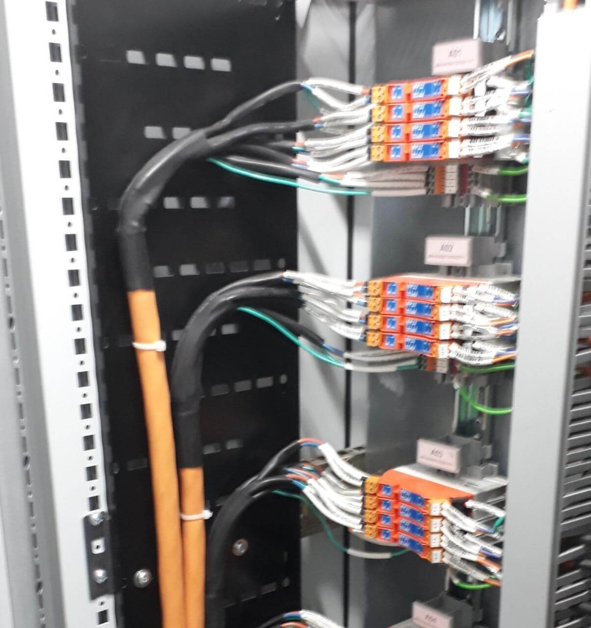
Fieldbus Panel bottom
Marshalling Cabinet End Termination. Type-2 FF Cable
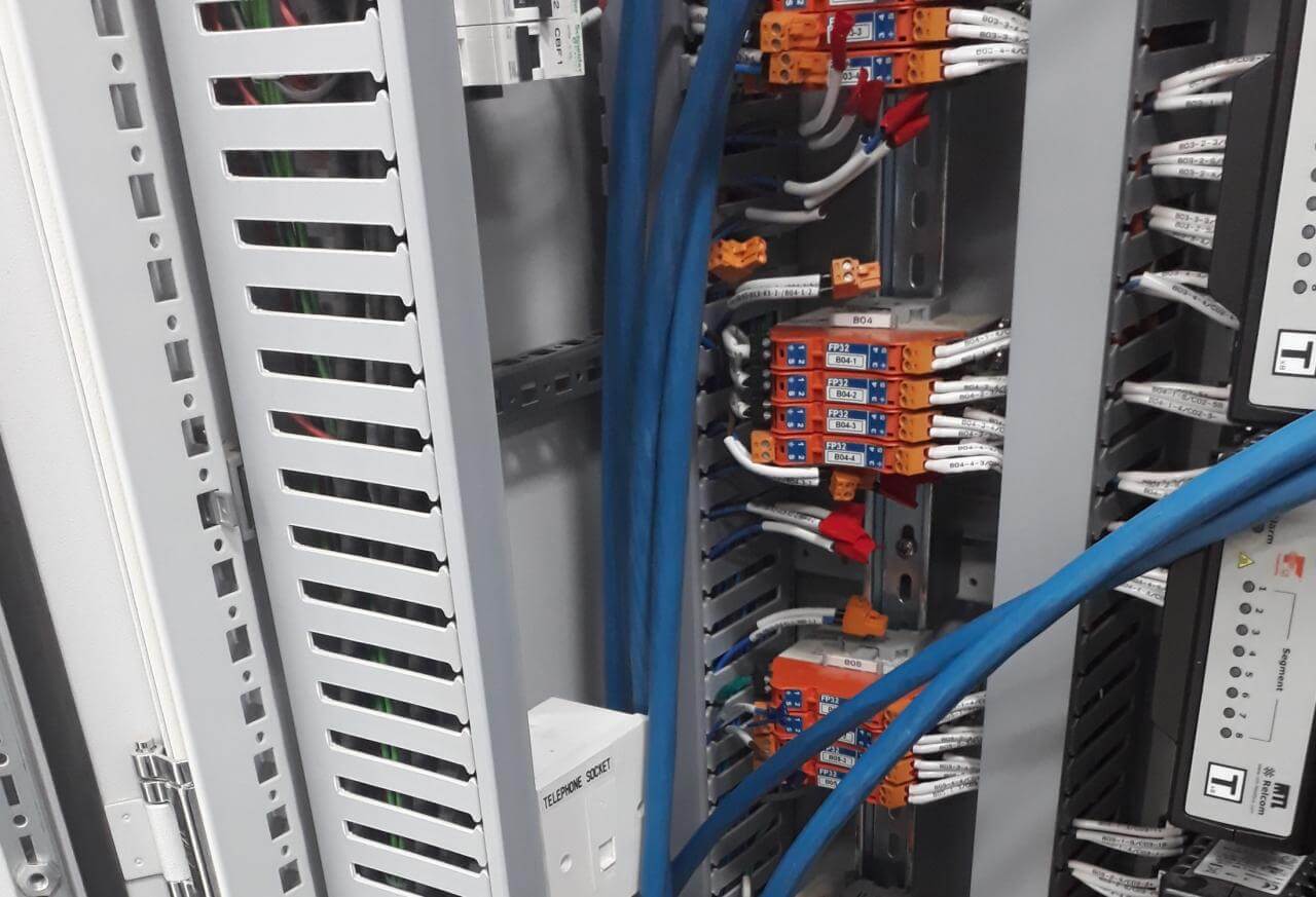
Panel bottom
Megablock JB Termination
Spur JB Termination
Multiplexer JB Termination
Intermediate JB Termination
Marshalling Cabinet Unistrut Clamp
Read Next:


many thanks for your efforts and very good explanation