WirelessHART technology brings a new dimension to the world of process automation. Building on the proven success of the HART Protocol, the WirelessHART extends the reach of process instrumentation in a way that is compatible with existing systems and practices.
Let’s review the straight-forward steps needed to ensure a successful WirelessHART installation.
Planning a WirelessHART Project
1.Scope the Project
- What are the objectives for the project – PV monitoring, non-critical control or Instrument condition monitoring. The answer to this question will affect the devices you select – battery powered instruments or WirelessHART adaptors for example. As part of the scope, be sure to review; area of network coverage, density of the area and primary and secondary instrumentation.
2.Planning the Network
- There are several ways by which you can plan a network and allocate devices. They are similar to those used when allocating instruments to I/O cards in a PLC/Controller, however, there are some new considerations such as gateway placement and update rates.
- WirelessHART could have little impact here, however there will be some things that are new. For example, the instrument data sheet and I/O schedule will need to reflect new information such as Network-ID – Join Key – Refresh Rate.
3.Host Integration
- Here the emphasis is upon using existing protocols (Modbus – Profibus) for host integration and existing tools for instrument configuration. The new consideration is security – which is built-in!
Device Placement
Don’t forget this is a mesh network. Instruments do not need to be within the range of the gateway but rather just need to be close to another wireless instrument.
Tips for Network Planning:
- Locate instruments based upon segmentation criteria
- Check coverage via scaled site drawing
- Locate repeaters as required
- The gateway can be moved into the plant (check for necessary certification)
- Use directional or remote antenna if needed
Device Specification
WirelessHART devices are all basically the same when it comes to their wireless characteristics. The device should be registered with the Foundation which is an indicator of a good wireless design and interoperability with other suppliers’ products.
Verify the range of the antenna since some devices may offer antenna options that will alter the distance assumptions.
Factory Configuration – Decide if you want the network ID and join key entered by your supplier (if offered)
Commissioning and Checkout
Planning a WirelessHART network is a fairly simple process. Common sense rules provide the guidance for a successful installation. Here are a few things to remember:
A HART handheld or PC tool will allow you to join instruments to the network. Overlapping networks will have different network ID’s.
1.Steps – the Gateway
-
- Install and power Gateway
- Install devices one by one
- Begin with closest to the gateway
2.Steps – the WirelessHART Device
-
- Install or activate the device’s power source
- Enter the Network ID
- Enter the Network Join Key
- Set the refresh (update) rate
- Verify the device has joined the network
- At the device using a handheld or other tool
- At the gateway
3.Steps – Commissioning a WirelessHART device
1.Verify Device Operation
- Check device TAG
- Check device engineering units
- Check PV Update rate
- Check battery voltage
2.Verify Gateway
- Check for minimum of 5 direct connections
- Check for 25% of devices with direct connections in large networks with <10% add repeaters if necessary
Commissioning a WirelessHART network
After all devices have been commissioned, allow time for the network to optimize (about 4 hours). Check each device for at least 3 neighbors and check path stability for 60% minimum. Increasing the elevation of the antenna can correct many situations and add a repeater if necessary.
Security
Allowing Access to the Network through Key Management including Network ID Key Management includes a global key for all devices, individual key for each device, Join Key – Fixed, Rotating or Assignment at the factory with order or on the bench. White Lists may include only “approved” devices allowed or requires an approval procedure
Best Practices
- Each field device has at least 3 neighbors. The 3rd neighbor will act as a backup if one of the two primary paths is obstructed or unavailable
- Devices (antenna) mounted >0.5m from any vertical surface
- Devices mounted >1.5m off the ground
- Gateway should have at least 5 neighbors
- 25% of the network devices should have a direction connection to the gateway in large networks
Device Commissioning
HART-based instruments have several features that significantly reduce the time required to fully commission a HART network or loop. Less time spent in device commissioning can result in substantial cost savings.
Device commissioning includes the time and cost-saving features:
- Streamlined and centralized device verification
- Easy loop integrity check
- As-installed record keeping
After commissioning, devices need to undergo configuration and calibration prior to use.
Device Verification
Before installation, manufacturers usually enter device tags and other identification and configuration data into each field instrument. This information is usually provided when the device is ordered. After installation, the instrument identification, the tag and descriptor, can be verified either on the workbench or in the control room using a device configurator, which can be a handheld communicator or PC using a modem connected to the device or to the 4-20mA loop.
Some field devices provide information on their physical configuration. For example the devices may deal with wetted materials, ratings or limits of different types.
Physical and other configuration data can be verified in the control room. The verification process is important for safety and in conforming to governmental regulations and ISO quality requirements.
The commissioning process can be further streamlined by connecting a PC-based configuration application to each HART loop. This can be done by integration with the control system or by using one of the many available HART multiplexing I/O systems. With this centralized approach, there is no need to move the configuration device from one termination point to the next while commissioning all devices on the network.
Loop Integrity Check
Once a field instrument has been identified and its configuration data confirmed, the analog loop integrity can be checked using the loop test feature, which is supported by many HART-enabled devices. The loop test enables the analog signal from a HART transmitter to be fixed at a specific value.
This fixed value verifies loop integrity and ensures a proper connection to support devices such as indicators, recorders, and DCS displays. This approach ensures a proper physical connection among all network devices.
Additional integrity can be achieved if the analog value is compared to the digital value being reported in a device. For example, someone might have provided an offset to the 4-20mA analog value that has not been accounted for in the control system. By comparing the digital value of the Primary Variable to the analog value, loop integrity can be verified.
As-Installed Record Keeping
Many HART configurators also facilitate record keeping. As-installed device configuration data can be stored in memory or on a disk for archiving or printing. This facilitates record keeping compliance and provides a documented trail of the configuration to simply device replacement.
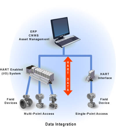
Integration of HART Data
There are many ways to integrate HART data and leverage the intelligence in smart field devices. These simple and cost-effective strategies include:
- Point-to-Point – This is the most common use of HART technology.
- HART-to-Analog – Integrate HART data with an existing analog control system by converting digital data into analog signals.
- HART-plus-Analog – A hybrid approach that keeps analog control but provides better device access.
- Full HART integration – A newer method with continuous communication between field device and control system.
- HART-to-Plant-Network – This powerful integration strategy passes HART data into plant Ethernet networks for use anywhere in an enterprise.
These data integration capabilities can save time and money, provide valuable diagnostic information, and allow field device data to be used plantwide in enterprise resource planning systems. Here are several ways to get more from currently installed HART equipment, running from the simplest to the most powerful.
Point-to-Point Integration – The most common use of HART technology. The communication capability of HART-enabled devices allows them to be configured and set-up for specific applications. This reduces spares inventory as well as saving time and money in commissioning and maintenance.
By connecting to the 4-20mA wires anywhere on the current loop, you can interrogate a device from remote locations. You can then obtain device status and diagnostic information.
HART-to-Analog Integration – Signal extractors communicate with HART devices in real-time to convert the intelligent information located in these devices into 4-20mA signals. These are then fed into an existing analog control system. Add this capability one device at a time to get more from your intelligent HART devices. Some of these devices also provide contact / alarm closures for early warning of potential problems.
HART-plus-Analog Integration – HART multiplexer package solutions make it easy to communicate with HART devices by replacing existing I/O termination panels. Your analog control signal continues on to the control system as it does today.
The HART data is lifted off the analog signal and sent to a device / asset management system providing valuable diagnostics information 24 hours a day 7 days a week. Although the controller is not aware of the HART data, this solution provides better access to device diagnostics for asset management or process improvements.
Full HART Integration – Upgrading your Field or Remote I/O system to one that is HART-enabled provides an integrated path to continuously put HART data directly into your control system. Most new control systems are HART-capable. Many suppliers offer software and I/O solutions to make upgrades simple and cost-effective.
Continuous communication between the field device and control system enables problems with a device, its connection to the process, or inaccuracies in the 4-20mA control signal to be detected automatically. Corrective action can be taken before there is negative impact to the process operation. This solution also provides the opportunity to move from a schedule-based maintenance strategy to a predictive-based maintenance strategy where devices notify the system of a potential problem – allowing you the ability to work on devices that only need attention.
HART-to-Plant Network Integration – The HART OPC Server software tool provides a simple, cost-effective means of passing HART data into your plant Ethernet network. Once there, the data can go to OPC-compliant applications anywhere in the plant.
Wire Length & Capacitance
Wiring HART Devices
In general, the installation practice for wired HART devices is the same as for conventional 4-20mA instrumentation. Guidelines for a wired HART installation involve:
- Using shielded twisted pair cabling with the proper conductor size
- Grounding at one point only
- Ensuring a properly specified power supply
- Staying below the maximum allowable cable length which depends upon the cable capacitance and the number of network devices.
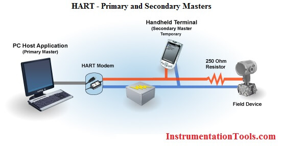
Typical Wiring Connection using a HART Field Device, a PC with a PC-based Application and a Handheld Terminal. Also shown is a required HART Interface or Modem – either RS232 or USB version.
Cabling considerations
If possible, use individually shielded twisted pair cable, either in single pair or multi-pair varieties. Unshielded cables may be used for short distances, provided ambient noise and cross-talk will not adversely impact communication. The minimum conductor size is 0.51mm diameter (#24 AWG) for cable runs less than 1,500 meters (@ 5,000 ft.) and 0.81mm diameter (#20 AWG) for longer distances.
Grounding
To prevent external interference, ground the system properly. In particular, the signal loop should be grounded, if at all, at one point only. The cable screening must be connected to ground, again at one point only. It must not be connected to instrument or junction box cases unless these are isolated from ground. The single ground point will usually be at or near the host – for example, at the control system.
Power supply voltage
Power for a two-wire instrument loop is typically 24V d.c. As always, the voltage must be sufficient to provide the necessary lift-off voltage for the field device. Take into account voltage drops in the cable and load resistor, as well as from any passive intrinsic safety, or IS, barrier present. Smart devices may take up to 22 mA to indicate an alarm condition. Use this value to calculate the worst loop voltage drop.
Power supply ripple and noise
The table below shows additional communication-related specifications for the power supply for a HART loop. The ripple and noise specifications prevent direct interference with the HART signals. The impedance limit ensures that HART signals see the power supply as a low impedance path. This prevents inadvertent coupling and crosstalk between multiple HART loops powered from a common supply. Include the resistance of output fuses, if any, when measuring this value
| Maximum ripple (47 to 125 Hz) | 0.2 V p-p |
| Maximum noise (500 Hz to 10 kHz) | 1.2 mV rms |
| Maximum series impedance (500 Hz to 10 kHz) | 10 Ω |
Cable length
Most installations are well within the 3,000-meter (10,000 ft) theoretical limit for HART communication. However, the electrical characteristics of the cable – primarily its capacitance – and the number of connected devices can affect the maximum allowable cable length. The table below shows the effect of cable capacitance and the number of network devices on cable length.
This is based on typical HART devices in non-IS, or intrinsic safety, environments, which means there is no miscellaneous series impedance. Detailed information for determining the maximum cable length for any HART network configuration can be found in the HART Physical Layer Specifications.
Cable Length – feet (meters)


What is the Time (Manhour) required for Installation of one Single Field Transmitter