Inst ToolsInst ToolsInst Tools
  • Courses
  • Automation
    • PLC
    • Control System
    • Safety System
    • Communication
    • Fire & Gas System
  • Instrumentation
    • Design
    • Pressure
    • Temperature
    • Flow
    • Level
    • Vibration
    • Analyzer
    • Control Valve
    • Switch
    • Calibration
    • Erection & Commissioning
  • Interview
    • Instrumentation
    • Electrical
    • Electronics
    • Practical
  • Q&A
    • Instrumentation
    • Control System
    • Electrical
    • Electronics
    • Analog Electronics
    • Digital Electronics
    • Power Electronics
    • Microprocessor
  • Request
Search
  • Books
  • Software
  • Projects
  • Process
  • Tools
  • Basics
  • Formula
  • Power Plant
  • Root Cause Analysis
  • Electrical Basics
  • Animation
  • Standards
  • 4-20 mA Course
  • Siemens PLC Course
Reading: Under and Over-Capacity Control Valve Pose Poor Controllability
Share
Font ResizerAa
Inst ToolsInst Tools
Font ResizerAa
  • Courses
  • Design
  • PLC
  • Interview
  • Control System
Search
  • Courses
  • Automation
    • PLC
    • Control System
    • Safety System
    • Communication
    • Fire & Gas System
  • Instrumentation
    • Design
    • Pressure
    • Temperature
    • Flow
    • Level
    • Vibration
    • Analyzer
    • Control Valve
    • Switch
    • Calibration
    • Erection & Commissioning
  • Interview
    • Instrumentation
    • Electrical
    • Electronics
    • Practical
  • Q&A
    • Instrumentation
    • Control System
    • Electrical
    • Electronics
    • Analog Electronics
    • Digital Electronics
    • Power Electronics
    • Microprocessor
  • Request
Follow US
All rights reserved. Reproduction in whole or in part without written permission is prohibited.
Inst Tools > Blog > Root Cause Analysis (RCA) > Under and Over-Capacity Control Valve Pose Poor Controllability

Under and Over-Capacity Control Valve Pose Poor Controllability

Instrumentation engineering root cause analysis (RCA) of under and over-capacity control valves pose poor controllability.

Last updated: September 28, 2022 3:02 pm
S Raghava Chari
Root Cause Analysis (RCA)
No Comments
Share
2 Min Read
SHARE

Instrumentation engineering root cause analysis (RCA) of under and over-capacity control valves pose poor controllability.

Contents
Under and Over Capacity Control ValveBenefits of the Solution
Article Type:Root Cause Analysis (RCA)
Category:Instrumentation
Equipment Type:Control Valves
Author:S. Raghava Chari

Note: This root cause analysis (RCA) is from real-time scenarios that happened in industries during the tenure of two or three decades ago. These articles will help you to improve your troubleshooting skills and knowledge.

Under and Over Capacity Control Valve

Two control valves posed problems (P) and the Author RCA solutions (S) are as under:

Problem:

Poor boiler drum level control because of just 15% open LCV 301

Solution:

Obviously poor controllability oversized control valve (CV).

Re-calibrate the 30-mm valve travel VP (valve positioner) for 20 mm travel and fix a new 20 mm marks scale.
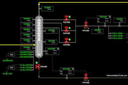
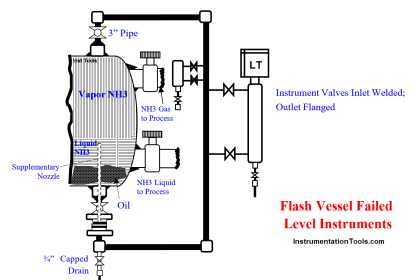
Problem:

Even with exit PCV 213 full open, First Flash Separator pressure was > SP

Solution:

Obviously, control valve (CV) opening is insufficient;

Re-calibrate the valve positioner (VP) from 35 mm to 55 mm and fit a 55 mm marking scale

Benefits of the Solution

Excellent control, saved new valves purchase costs, and commissioning proceeding on schedule.

Author: S. Raghava Chari

Do you face any similar issues? Share with us through the below comments section.

If you liked this article, then please subscribe to our YouTube Channel for Instrumentation, Electrical, PLC, and SCADA video tutorials.

You can also follow us on Facebook and Twitter to receive daily updates.

Read Next:

  • Valve Positioners Failed
  • Errors and Faults in Siemens PLC
  • Repeat Failures of Letdown Valves
  • Pressure Taps Block Valves Leaks
  • Unstable & Drifting Values of Transmitter
Don't Miss Our Updates
Be the first to get exclusive content straight to your email.
We promise not to spam you. You can unsubscribe at any time.
Invalid email address
You've successfully subscribed !

Continue Reading

Heat Exchanger Tubes Corroded Root Cause Analysis
Repeat Control Valve Plug Stem and Gland Leaks
Root Cause Analysis for Plant Trip Due to Work on Incorrect Tag
Turbine to Gearbox Alignment Drifts Caused Pump Transfers Problems
Pitot-tube Replaced with Innovative Segment Orifice Plate
Thermocouple Extension Lead Problem
Share This Article
Facebook Whatsapp Whatsapp LinkedIn Copy Link
Share
Leave a Comment

Leave a Reply Cancel reply

Your email address will not be published. Required fields are marked *

Stay Connected

128.3kFollowersLike
69.1kFollowersFollow
210kSubscribersSubscribe
38kFollowersFollow

Categories

Explore More

CO2 Absorber Corroded Wall Thickness & Weld Building
Problem with Choked Control Valve with Whisper Trim Cage
Failing Weigh Feeders and Mechanical Variable Speed Drives (VSD)
Learnings from the BP Refinery Explosion at Texas City
Compressor Anti-Surge Control near-miss incident
Thermowell Shank to Flange Repeat Weld Leaks
Pressure Switch Frozen Screwed Cover Extends the Plant Shutdown
Doubtful Temperature Readings threatens Soaking Pit Wrecks 

Keep Learning

HT motors Corrosion Problem

HT motors Corrosion Problem

Sprocket Assembly and Bolting Segments

Bucket elevators Chain and teeth wear Problems

Poorly Built Switchgears

Poorly Built Switchgears – Why Breaker Parts Tear apart or don’t work?

Root Cause Analysis of Differential Pressure Level Transmitter

Root Cause Analysis of Differential Pressure Level Transmitter

Thermocouples Problem

Fire burnt Ammonia Converter Thermocouples Problem

Induced Draft Cooling Tower

Cooling Tower fan FRP fan blades saves and saves

Repeat Safety Valve Popping

Repeat Safety Valve Popping caused Urea Plant Shutdown

Incident Investigation: Motor Operated Valve Lesson

Incident Investigation: Motor Operated Valve Lesson

Learn More

How to Read and Understand an Electrical Single Line Diagram?

How to Read and Understand an Electrical Single Line Diagram?

Electronic Force Balance Pressure Transmitter

Electronic Force Balance Pressure Transmitter

Flapper nozzle system

What is Flapper Nozzle System ?

Diagnosing the Electric Motor Circuit

Diagnosing Electric Motor Circuit

Control system architecture diagrams

Vendor Document for Project Systems Architecture

Electric Circuits Objective Questions

Electric Circuits Objective Questions – Set 4

Streams After Electrical Engineering Graduation

Streams After Electrical Engineering Graduation

FOUNDATION Fieldbus junction boxes

Fieldbus Cables

Menu

  • About
  • Privacy Policy
  • Copyright

Quick Links

  • Learn PLC
  • Helping Hand
  • Part Time Job

YouTube Subscribe

Follow US
All rights reserved. Reproduction in whole or in part without written permission is prohibited.
Welcome Back!

Sign in to your account

Username or Email Address
Password

Lost your password?