Inst ToolsInst ToolsInst Tools
  • Courses
  • Automation
    • PLC
    • Control System
    • Safety System
    • Communication
    • Fire & Gas System
  • Instrumentation
    • Design
    • Pressure
    • Temperature
    • Flow
    • Level
    • Vibration
    • Analyzer
    • Control Valve
    • Switch
    • Calibration
    • Erection & Commissioning
  • Interview
    • Instrumentation
    • Electrical
    • Electronics
    • Practical
  • Q&A
    • Instrumentation
    • Control System
    • Electrical
    • Electronics
    • Analog Electronics
    • Digital Electronics
    • Power Electronics
    • Microprocessor
  • Request
Search
  • Books
  • Software
  • Projects
  • Process
  • Tools
  • Basics
  • Formula
  • Power Plant
  • Root Cause Analysis
  • Electrical Basics
  • Animation
  • Standards
  • 4-20 mA Course
  • Siemens PLC Course
Reading: Control Valve Passing Problem after Overhauling Job
Share
Font ResizerAa
Inst ToolsInst Tools
Font ResizerAa
  • Courses
  • Design
  • PLC
  • Interview
  • Control System
Search
  • Courses
  • Automation
    • PLC
    • Control System
    • Safety System
    • Communication
    • Fire & Gas System
  • Instrumentation
    • Design
    • Pressure
    • Temperature
    • Flow
    • Level
    • Vibration
    • Analyzer
    • Control Valve
    • Switch
    • Calibration
    • Erection & Commissioning
  • Interview
    • Instrumentation
    • Electrical
    • Electronics
    • Practical
  • Q&A
    • Instrumentation
    • Control System
    • Electrical
    • Electronics
    • Analog Electronics
    • Digital Electronics
    • Power Electronics
    • Microprocessor
  • Request
Follow US
All rights reserved. Reproduction in whole or in part without written permission is prohibited.
Inst Tools > Blog > Control Valves > Control Valve Passing Problem after Overhauling Job

Control Valve Passing Problem after Overhauling Job

Root Cause Analysis for Control Valve passing problem which was started after the overhauling job.

Last updated: August 15, 2023 6:52 am
Editorial Staff
Control Valves Root Cause Analysis (RCA)
No Comments
Share
6 Min Read
SHARE

Root Cause Analysis for Control Valve passing problem which was started after the overhauling job.

Contents
Control Valve Passing ProblemObservations of the Job on Control ValveWhat Went Wrong with the Control Valve?Solution

Control Valve Passing Problem

Control Valve Passing Problem after Overhauling Job

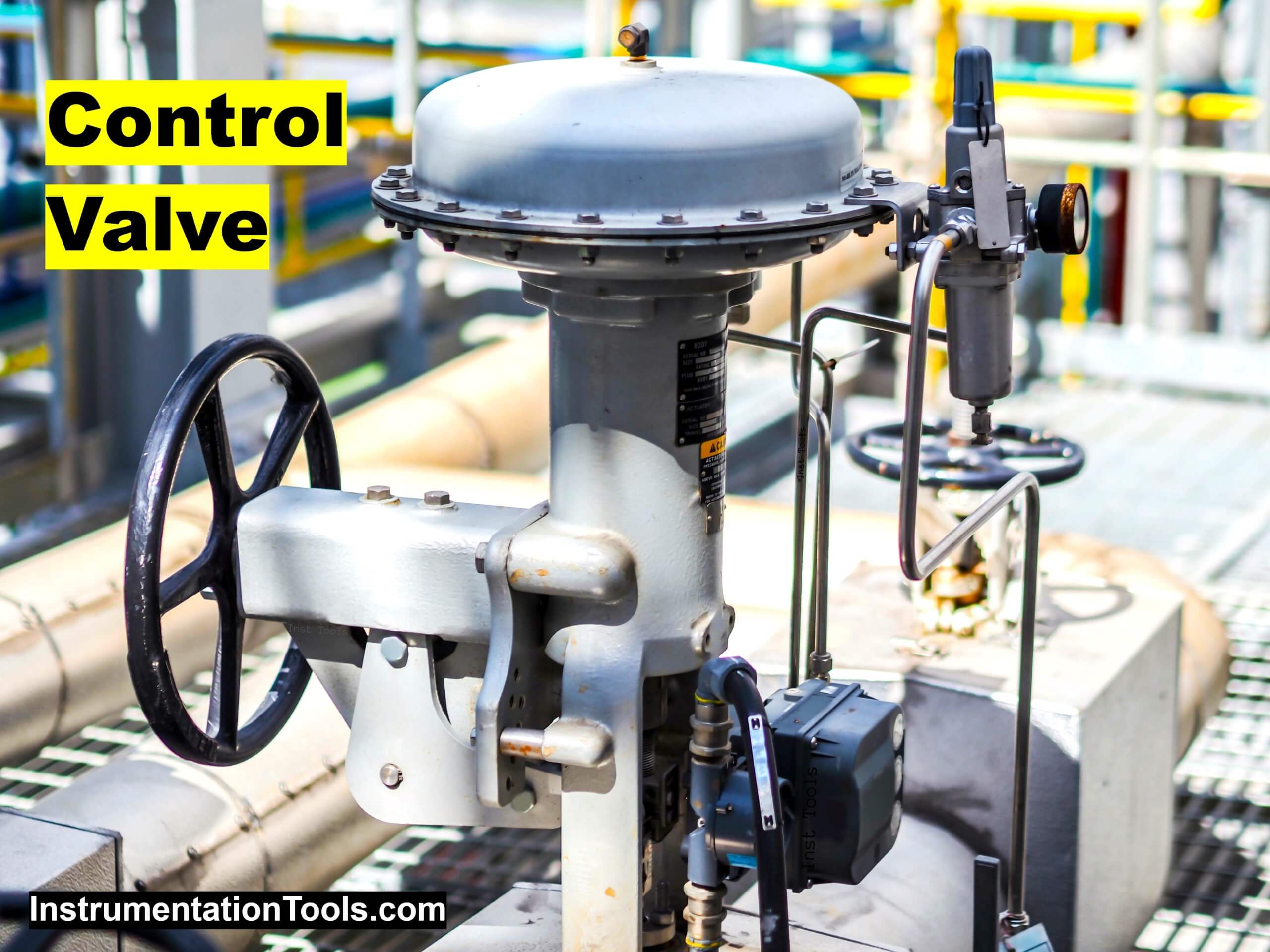
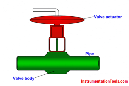
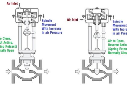
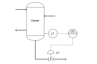
A control valve (globe valve with air to close – diaphragm type actuator) installed in the dirty water service was having major passing issues. So to attend to the passing of the control valve, an overhauling job was taken.

The control valve was properly overhauled in the workshop. After overhauling, stroke checking was done in the workshop itself after a calibration. The calibration type was auto-calibration.

The control valve was having Class IV leakage class. As per class IV, a leakage test was done and the response of the control valve was satisfactory. The control valve was shifted to a new location and installed back.

After taking the control valve inline, again passing was observed. So what went wrong? Let us have a detailed analysis of the scenario.

Probable Cause 1: Control valve having seat or plug damage

Overhauling was done recently and all hard parts of the repair kit were replaced. The control valve was single-line equipment and the control valve was not overhauled for the last 10 years.

Probable Cause 2: Control valve having actuator passing issue

Overhauling was done recently and all soft parts were replaced as the control valve was single-line equipment.

Also, as mentioned above cause, the control valve was not overhauled for the last 10 years.

Probable Problem 3: Control valve having a calibration issue

After the overhauling job, the control valve was auto-calibrated at the workshop itself. The stroke was checked and the response was satisfactory.

Also as per the control valve’s design leakage class, the leakage test was done at the test bench. There was no passing observed.

Probable Problem 4: Damage to the control valve during shifting of the control valve to the location

The control valve was shifted properly with all necessary precautions under the observation of a supervisor and an engineer.

Probable Problem 5: Control valve’s actuator not having proper air supply pressure

Air supply pressure to the actuator was checked and found ok as per the datasheet of the control valve.

Observations of the Job on Control Valve

Observations after taking the control valve for maintenance job again:

  1. The control valve’s air supply pressure was checked and found ok.
  2. The control valve’s actuator was checked and no passing was found.
  3. After isolating the line and checking the stroke of the control valve, it was found that the control valve’s stroke length was less than 100%. Because of this less stroke length, the control valve remained open, and hence passing was observed.
  4. The control valve was again auto-calibrated. This time the operating stroke length was verified as per the data sheet. The response was satisfactory. Also, the control valve was taken inline. No passing was observed at full design differential pressure across the control valve. 

What Went Wrong with the Control Valve?

The engineer and the technician, who installed the control valve, were asked about the whole process of installation (Because no mistake was made at the workshop).

On a healthy conversation with the engineer, the team came to know that the control valve was again auto-calibrated at the site after installation.

The reason behind again auto-calibrating the control valve was that after installing the control valve and taking the control valve inline, the control valve was having a hunting issue (2% – 3% hunting). So the supply air pressure was checked and found ok.

The actuator was also ok. So, the engineer decided to auto-calibrate the control valve. So, the line was again isolated and the control valve was auto-calibrated.

The probable reason can be that during the auto-calibration job when the control valve was in line, some foreign material might have been deposited on the seat as the control valve was installed in a dirty water service which has some hard particles also.

So because of this foreign material, the control valve could not fully close and hence the full stroke was less as compared to the original stroke length.

When the control valve was again taken inline, due to the pressure of the water, the foreign material might have gone in downstream creating a space for leakage.

Solution

How can we avoid such issues?

  1. Always mark the full stroke length and verify it with the stroke length mentioned in the datasheet.
  2. Do proper line flushing with clean water or air before calibrating the control valve.

If you liked this article, then please subscribe to our YouTube Channel for Instrumentation, Electrical, PLC, and SCADA video tutorials.

You can also follow us on Facebook and Twitter to receive daily updates.

Read Next:

  • Quick Exhaust Valves
  • On-Off Valve Problems
  • Control Valve Design Factors
  • Solenoid and Motorized Valves
  • Control Valve Maintenance
Don't Miss Our Updates
Be the first to get exclusive content straight to your email.
We promise not to spam you. You can unsubscribe at any time.
Invalid email address
You've successfully subscribed !

Continue Reading

Fluid Power Systems
What is Mixing or Diverting Valve ?
Basics of Ball Valves
Difference between PCV and PRV
How-to do Control Valve Calibration?
Control Valve Air Lock Relay Working Principle
Share This Article
Facebook Whatsapp Whatsapp LinkedIn Copy Link
Share
Leave a Comment

Leave a Reply Cancel reply

Your email address will not be published. Required fields are marked *

Stay Connected

128.3kFollowersLike
69.1kFollowersFollow
210kSubscribersSubscribe
38kFollowersFollow

Categories

Explore More

Cavitation Test Setup
Solenoid Valve Functional Testing
Root Cause Analysis for Plant Trip Due to Work on Incorrect Tag
Locked Open (LO) and Locked Closed (LC) Valves
5 Port 2 Position Valve Working Principle
Plant Air Storage Tank Pressure Fluctuations Root Cause Analysis
Free Control Valves Course
What is Instrument Air Manifold ?

Keep Learning

Amine Pump Trip - Root Cause Analysis

Amine Pump Trip – Root Cause Analysis

Control Valve with Positioner

 Control Valve Accessories – Principle, Purpose, Advantages

What is an Actuator - Different Types of Actuators

What is an Actuator? – Different Types of Actuators

JT Valve Working Principle

JT Valve Working Principle

Erratic Stroking Control Valves

Erratic Stroking Control Valves Delaying the Shutdown Plant Restart

Air Cylinder Consumption Calculation for Control Valves

Air Cylinder Consumption Calculation for Control Valves

Y Body Globe Valve

Globe Valve Body Design

Target Flow Transmitter Problem

Target Flow Transmitters Failed the Very Midnight

Learn More

Components of SCADA

Components of SCADA

Thermocouple Temperature Ranges

Thermocouple Temperature Range Questions and Answers

Process Control Instrumentation Objective Questions

Process Control & Instrumentation Objective Questions – Set 4

annunciator-alarm-simulator

Alarm Simulator for Annunciator Logic

Seebeck Effect

Seebeck Effect Theory

State Variable Analysis and Design

State Models for Linear Continuous Time Systems

PLC Based Metro Automation Project

PLC based Metro Automation Project

PID Block in RSLogix 500

PID Block in RSLogix 500

Menu

  • About
  • Privacy Policy
  • Copyright

Quick Links

  • Learn PLC
  • Helping Hand
  • Part Time Job

YouTube Subscribe

Follow US
All rights reserved. Reproduction in whole or in part without written permission is prohibited.
Welcome Back!

Sign in to your account

Username or Email Address
Password

Lost your password?