This article is about controlling a motor automatically i.e., both Start and Stop automatically with help of timers.
Primarily, this operation is used to save manual time. This process starts with the Start Switch once pressed, then the motor will turn ON and OFF automatically with two timers.
There is a Stop Switch to stop the process at any time or in an emergency situation. Once the Stop switch is pressed, the process will start by pressing the Start Switch.
Components
- Miniature Circuit Breaker (MCB)
- Contactor
- Timer
- Control Switch
- Start Switch
- Stop Switch
- Multimeter
- Clamp meter
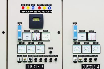
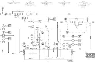
Motor Control Timer Circuit
This Automatic ON and OFF control of the motor have two circuits.
They are:
- Power Circuit
- Control Circuit
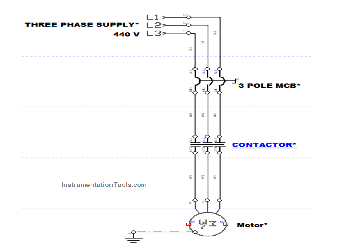
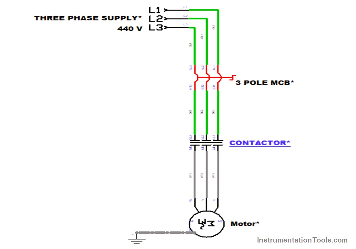
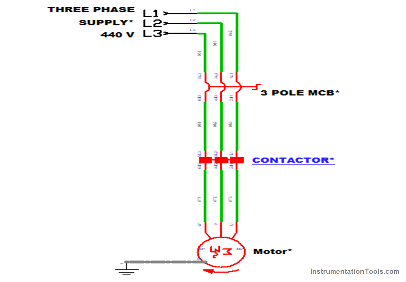
Power Circuit
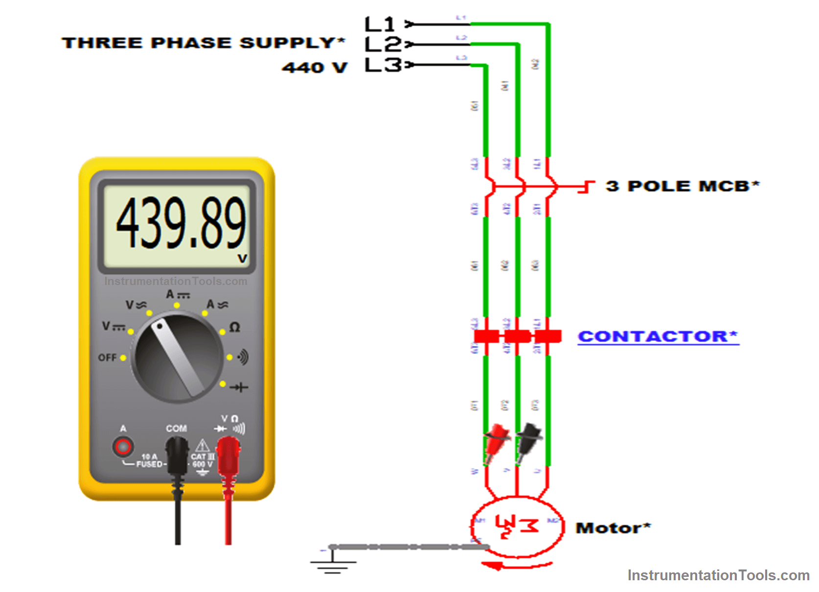
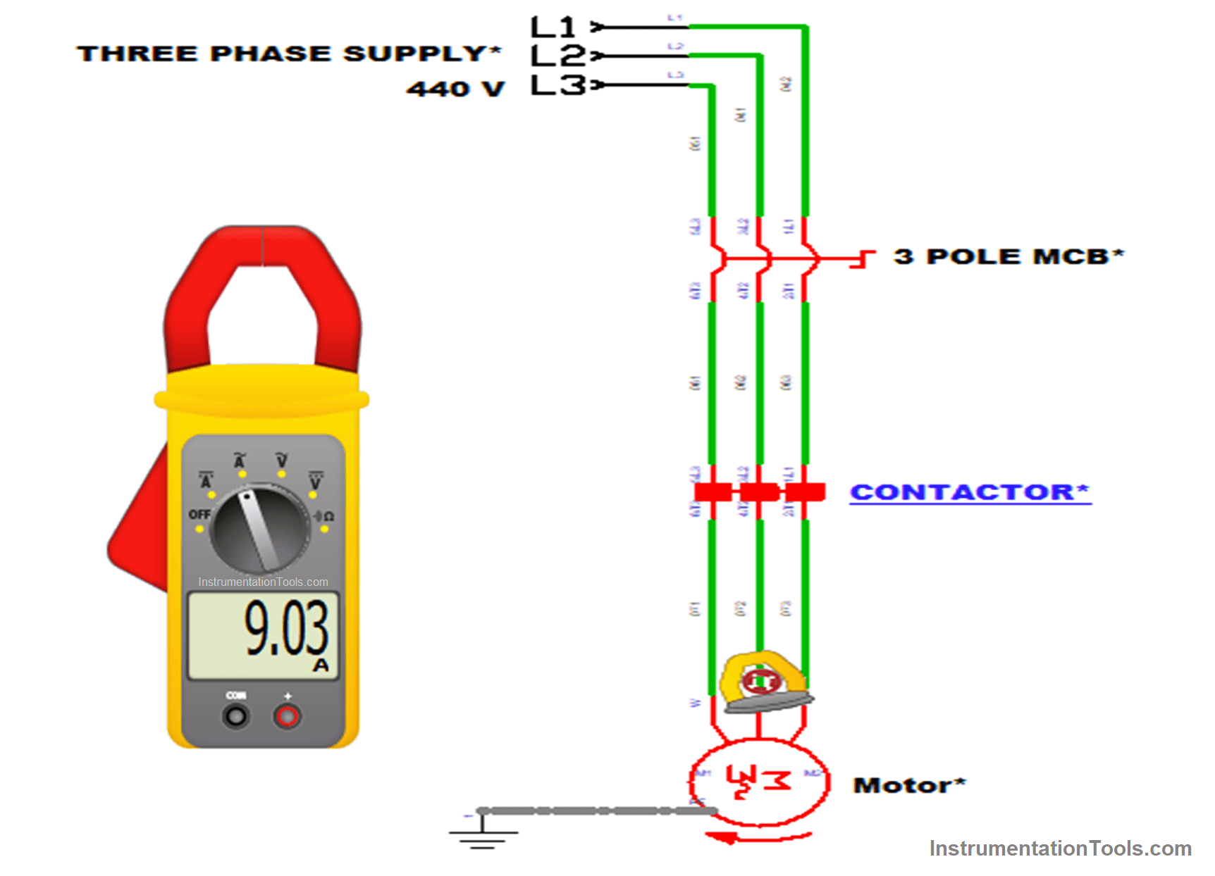
Three Phase supply of 440 V is used in this power circuit.
The power circuit mainly consists of the 3 pole MCB to prevent from excess power, Contactor for connecting & disconnecting the power to load, and the motor
Control Circuit
The single Phase supply of 240V is used as control voltage here. The main components in this circuit are the Stop and Start switches for giving the supply to the control elements.
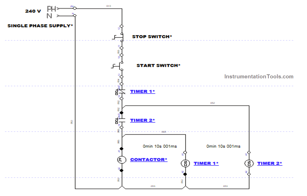
Two timers were used for automatic On and Off and the contactor coil for controlling the contactor in the power circuit.
Automatic Motor START and STOP using Timers
440 V supply voltage is given to the circuit for controlling the motor through 3 pole MCB and Contactor.
MCB is an electromechanical device that will trip automatically when excess power is passed in the circuit.
The contactor is a type of relay which is used to make the circuit open and close. Now, Turn ON the MCB.
Here Start switch is pressed in the control circuit, and the control voltage of 240 V is passed through the Start and Stop switches.
This supply passed through the NC (Normally Closed) contact of Timer1. It will give supply to Timer 2, now Timer 2 got energized. The time starts to run on the timer.
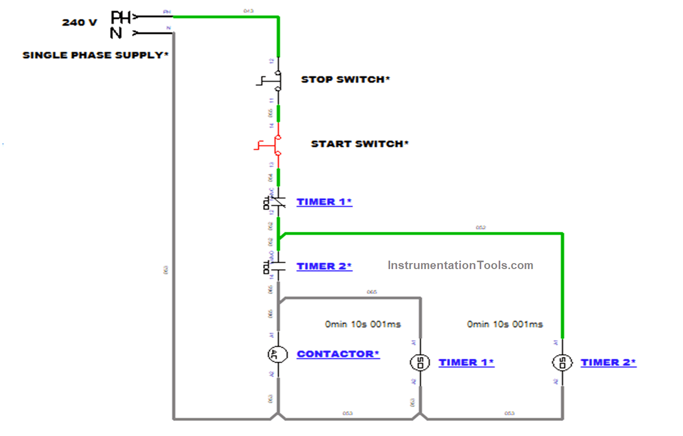
When the Pre-set value in Timer 2 meets the actual value, the NO (Normally Open) contacts will get powered. This will energize the Contactor and Timer 1.
Now the time starts to run in Timer 1.
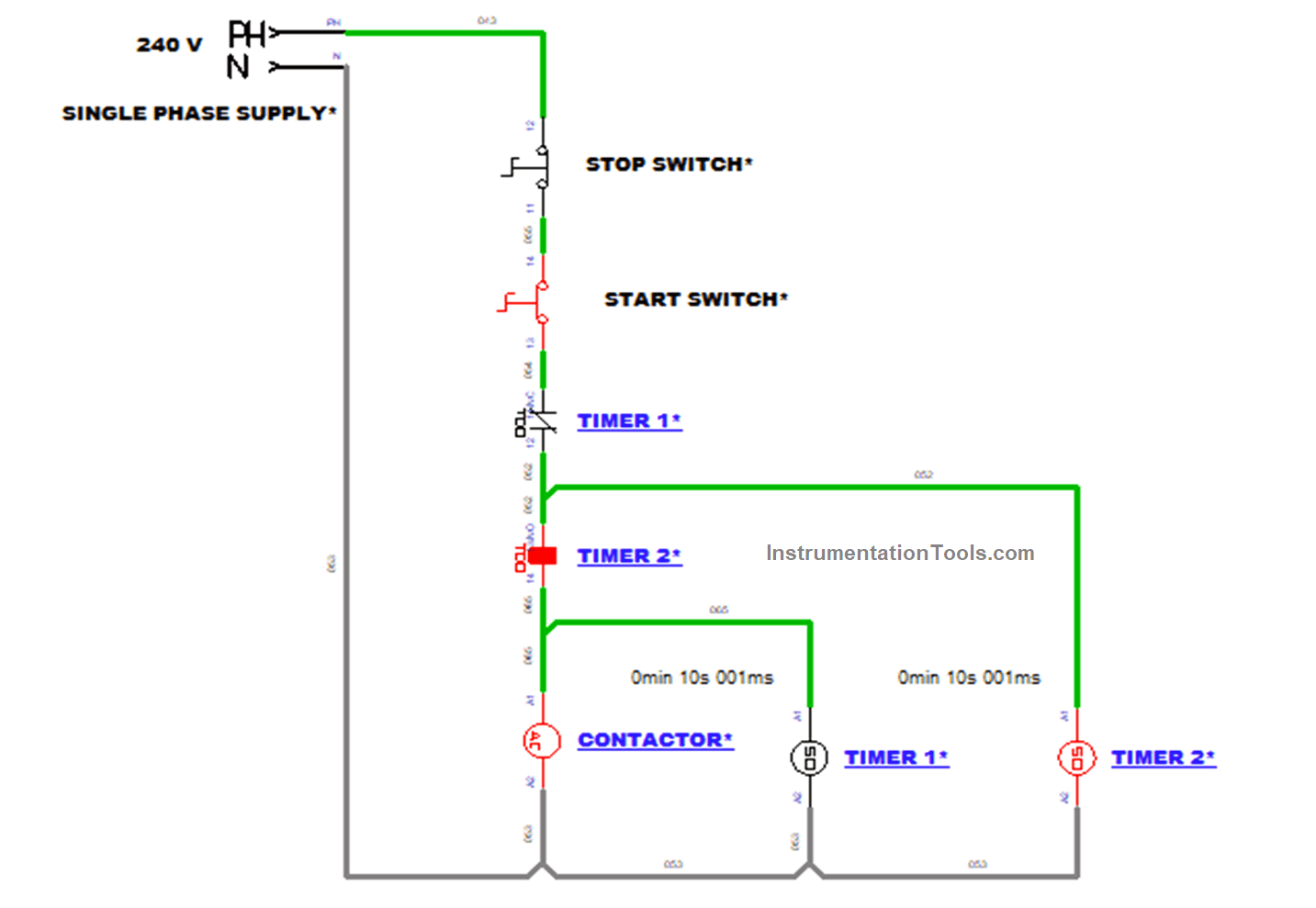
Energization of the contactor coil in the control circuit will make the contactor activate in the power circuit.
Thus, the contactor connects the supply to the motor. Now motor starts to rotate after some delay.
Now Timer 1 and the contactor are energized. So Time was started to run in Timer 1 when the actual time meets the present time in Timer 1. Its coil and contact will get activated.
When Timer 1 NC (Normally closed) Contact gets activated, it breaks all the supply going to Contactor 1, Timer 1, and Timer 2.
Now all the coils are de-energized. Since all the coils are de-energized all of its contacts also get de-activated and all will come back to the normal state within a fraction of a second.
At last in this, Contactor and Timer 1 will be in OFF state, and Timer 2 will be in ON state.
After the Timer operation in the previous steps, the Contactor coil got de-energized.
This makes the contactor to deactivate in the power circuit. Thus, the power supply going to the motor was broken and the motor stops rotating.
Now the motor stops automatically.
Hence, the process is repeated from the set time and the motor starts and stops automatically.
The two main factors in the circuit are Current and Voltage. We can measure them by using measurement devices like Multimeter and Clamp-meter.
In this circuit, Voltage is measured with the help of a multimeter. For measuring voltage connect the two probes of the multimeter in any of the two lines by setting the knob at V~. The measured voltage will be displayed on display.
For measuring current, Clamp-meter is used. Clamp-meter is nothing but a current transformer used for measuring current under load.
In the below circuit, the clamp meter was placed in any one of the lines by placing the hook-shaped clamp in it. Then the measured value will have displayed in the display.
Simulation
In the below video, we simulated the above-discussed motor control timer circuit.
If you liked this article, then please subscribe to our YouTube Channel for Instrumentation, Electrical, PLC, and SCADA video tutorials.
You can also follow us on Facebook and Twitter to receive daily updates.
Read Next:


How to control motor using arduino