Inst ToolsInst ToolsInst Tools
  • Courses
  • Videos
  • Q & A
    • Interview
      • Instrumentation
      • Electronics
      • Electrical
      • Practical Questions
    • MCQ
      • Instrumentation MCQ
      • Electrical MCQ
      • Electronics MCQ
      • Control Systems MCQ
      • Analog Electronics MCQ
      • Digital Electronics MCQ
      • Power Electronics MCQ
      • Microprocessor MCQ
      • Multiple Choice Questions
  • EE
    • Electronics
      • Electronics Q & A
      • Electronic Basics
      • Electronic Devices & Circuits
      • Electronics Animation
      • Digital Electronics
    • Electrical
      • Electrical Basics
      • Electrical Q & A
      • Power Electronics
      • Electrical Machines
      • Electrical Animation
      • Power Systems
      • Switchgear & Protection
      • Transmission & Distribution
  • Measure
    • Control Valves
    • Calibration
    • Temperature
    • Pressure
    • Flow
    • Level
    • Analyzers
    • Switches
    • Vibration
    • Solenoid Valve
  • Control
    • PLC Tutorials
    • Control Systems
    • Safety Instrumented System (SIS)
    • Communication
    • Fire & Gas System
  • More
    • Design
    • Tools
    • Animation
    • Basics
    • Formulas
    • Standards
    • TextBooks
    • Common
    • Software
    • Excel Tools
    • Erection & Commissioning
    • Process Fundamentals
    • Videos
    • Books
Search
All rights reserved. Reproduction in whole or in part without written permission is prohibited.
Reading: Arc Fault Breaker (AFB) Electrical Problem Solved
Share
Notification Show More
Font ResizerAa
Inst ToolsInst Tools
Font ResizerAa
  • Courses
  • PLC Tutorials
  • Control Systems
Search
  • Courses
  • Videos
  • Q & A
    • Interview
    • MCQ
  • EE
    • Electronics
    • Electrical
  • Measure
    • Control Valves
    • Calibration
    • Temperature
    • Pressure
    • Flow
    • Level
    • Analyzers
    • Switches
    • Vibration
    • Solenoid Valve
  • Control
    • PLC Tutorials
    • Control Systems
    • Safety Instrumented System (SIS)
    • Communication
    • Fire & Gas System
  • More
    • Design
    • Tools
    • Animation
    • Basics
    • Formulas
    • Standards
    • TextBooks
    • Common
    • Software
    • Excel Tools
    • Erection & Commissioning
    • Process Fundamentals
    • Videos
    • Books
Follow US
All rights reserved. Reproduction in whole or in part without written permission is prohibited.
Inst Tools > Blog > Root Cause Analysis (RCA) > Arc Fault Breaker (AFB) Electrical Problem Solved

Arc Fault Breaker (AFB) Electrical Problem Solved

Electrical engineering root cause analysis (RCA) related to Arc Fault Breaker (AFB) and its problem solved.

Last updated: September 28, 2022 3:08 pm
S Raghava Chari
Root Cause Analysis (RCA)
No Comments
Share
6 Min Read
SHARE

Electrical engineering root cause analysis (RCA) related to Arc Fault Breaker (AFB) and its problem solved.

Contents
Arc Fault Breaker ProblemThe author taken stepsRealized Benefits
Article Type:Root Cause Analysis (RCA)
Category:Electrical
Equipment Type:Bus ducts, Switchgear, Transformers,
Author:S. Raghava Chari

Note: This root cause analysis (RCA) is from real-time scenarios that happened in industries during the tenure of two or three decades ago. These articles will help you to improve your troubleshooting skills and knowledge.

Arc Fault Breaker Problem

Shock Pulse Meter (SPM) readings entering the yellow zone within 6 months and the red zone within a month from then required too often bearing changes and resulted in production loss and heavy maintenance expenses.

The electrical and even most mechanical crew accepted it as a way of life attributing spurious bearings prevalence, though the company bought bearings from manufacturer authorized outlets only.

The author carefully studied Arc Fault Breaker (AFB) catalogs to refresh his AFB know-how.

The following appealed to him:

  1. Designers select bearings for 7x24x365 machines for 50, 000 hours to 200, 000 hours i.e. 5.7 to 22.8 years – a year = 8760 hours –  depending on service criticalities
  2. 10% of so selected AFBs may serve 5 times the selected lives
  3. One should minimize heat generation by vendor recommended adequate lubrication
  4. Crew must replace failed bearings with basic + equipment maker specified prefix and or suffix numbers, and not by basic numbers, which only often punched on bearings. 

The author read these lines from the catalogs and urged the group to do their best to realize similar Arc Fault Breaker (AFB) lives.

He pointed out several never dissembled six years servicing equipment AFBs good SPM readings. However, the group seemed still skeptical.     

The author taken steps

The author observed bearing replacements and noted the following:

  1. Crew had to apply several shifts of unauthorized violent methods to extract coupling halves (CH) and failed AFBs; mostly they fail and finally resort to flame cutting both.
  2. The above process often injures the shafts and necessitates shaft repairs or even making new shafts
  3. Almost all AFBs / CH on shop made / repaired shafts had to be flame cut

The above 3 factors opened the Author’s eyes! He checked with the shop engineer and found that machinists machine shafts dia for 80 to 100 microns interference fit AFBs/CHs!

Obviously, this is far higher than the AFB catalogs specified transition fit by machining the shaft for m6 tolerance. This works out for a thumb rule figure of 1/7 micron / mm shaft dia clearance or interference for the common 25 to 150 mm bore AFBs / coupling halves. 

The author read these to the crew and urged fitting Arc Fault Breaker (AFBs) and CH accordingly.

He instructed further the following to realize the objectives:

  1. Do not flame heat AFB or CH for insertion
  2. Ensure shaft dia is of m6 tol for bearings and k7 for couplings and coupling bore tol H7
  3. Soak AFB / CH in oil bath held at 80o C hotter than room temperature for 5 to 10 min
  4. Remove the AFB / CH, wipe the bore and shaft seat oil free, insert the AFB / CH and allow to cool. Complete other steps if any.
  5. If the parts don’t fit easily check dimensions and correct
  6. Inject grease every 2000 / 1000 hours for 4 / 2 pole motors;
  7. Wash the old grease every 36 / 18 months with suitable solvents and refill fresh grease 2/3 the bearing volume and assemble the machine. Do not remove bearings from the shafts.
  8. SPM Monitor bearing condition at site experience determined frequency. Schedule and replace AFBs within a month on noting yellow zone readings.
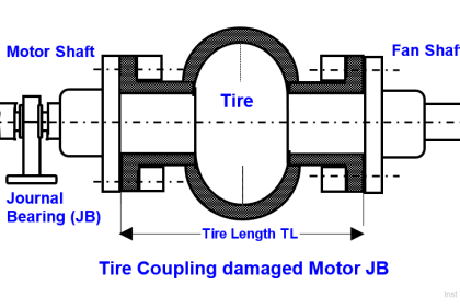
  9. Select Proper couplings – e.g. pin and bush couplings in place of tire couplings for sleeve bearing motors.

Realized Benefits

The realized benefits are;

  1. Arc Fault Breaker (AFB) lives exceeded design lives i.e. far fewer AFB changes and far more on stream hours
  2. Failed AFB and CH removal was easy and anyone did it.  No more waiting for the ‘experts’ and they too failing in most cases

Author: S. Raghava Chari

Do you face any similar issues? Share with us through the below comments section.

If you liked this article, then please subscribe to our YouTube Channel for Instrumentation, Electrical, PLC, and SCADA video tutorials.

You can also follow us on Facebook and Twitter to receive daily updates.

Read Next:

  • Poorly Built Switchgears
  • Failing Weigh Feeders and Drives
  • Frequent Lightning Arrester Burst
  • 110 KV Connection to Feeder A
  • Transformer Electrical Problem Solved
Don't Miss Our Updates
Be the first to get exclusive content straight to your email.
We promise not to spam you. You can unsubscribe at any time.
Invalid email address
You've successfully subscribed !

Continue Reading

Stuck Segment Orifice Dimensions Calculations
Antifriction Bearings Caused Machine Changeovers Posed Outages
RCA Related to Trip Throttle Valve (TTV)
Cooling Tower Fans Frequently Failing
Thermowell Shank to Flange Repeat Weld Leaks
Target Flow Transmitters Failed the Very Midnight
Share This Article
Facebook Whatsapp Whatsapp LinkedIn Copy Link
Share
Leave a Comment

Leave a Reply Cancel reply

Your email address will not be published. Required fields are marked *

Stay Connected

128.3kFollowersLike
69.1kFollowersFollow
208kSubscribersSubscribe
38kFollowersFollow

Categories

Explore More

Bucket elevators Chain and teeth wear Problems
Erratic H2 Flow Rotameter
Captive Power Plant Trip Root Cause Analysis
Discharge Head 3‑monthly leaks of Steam Turbine Driven Centrifugal Compressors
High-pressure Service Level Transmitters Misunderstood Zero Drifts
Transformers Coolers Weld Joints Oil Oozes Were Eye Sores
Cooling Water Circulating Pump Low throughput Resolved
Cooling Tower fan FRP fan blades saves and saves
Wrong Operation Internals Destroyed Demineralization Mixed Bed Vessel
Poorly Engineered, built & often Failing Plant Air Compressor Drives

Keep Learning

Surface Condenser Condensate Evacuation Pumps

Condensate Pump Frequent Wrecks Threatens Long Plant Outages

Fan Motor Frequent Journal Bearing Failures

Fan Motor Frequent Journal Bearing Failures Posed Plant Outages

Inability to Test Repaired HT Motors

Inability to Test Repaired HT Motors in Workshop Posed Problems

CO2 Stripper Old Differential Pressure Transmitter Stopped Working

CO2 Stripper Old Differential Pressure Transmitter Stopped Working

Improved Sprocket Segment Bolting to body

A Plant Bucket Elevators chains too short chain lives problem eliminated

Ball Valve root cause

Ammonia Feed Ball Valve to Ship Tank Closed

butt weld end Plug Valves Leaks Stopped

PTFE lined 6” 300# butt weld end Plug Valves Leaks Stopped Forever

Root Cause Analysis for Valve Problem

Root Cause Analysis for Tank Overflow due to Valve Problem

Discover More

Thermocouple Calculations

Thermocouple Calculations

Radar and Ultrasonic Level Transmitter Problems Troubleshooting

Radar and Ultrasonic Level Transmitter Practical Problems Troubleshooting

Temperature Switch

Temperature Switch Working Principle

Explain What these Spool Valve Represent

Explain What these Spool Valve Symbols Represent?

Baffle Nozzle Question

Baffle Nozzle Question

What is Oscilloscope

What is Cathode Ray oscilloscope ?

Dry Leg

Calculate 0%, 50%, and 100% Calibration Points for ΔP transmitter

Closed Tank Non-Zero-Based Direct Mount Application

Open and Closed Tank Level Calculations

Follow US
All rights reserved. Reproduction in whole or in part without written permission is prohibited.
Welcome Back!

Sign in to your account

Username or Email Address
Password

Lost your password?