In industry, there are many applications in which we use limit switches. Here we have one limit switch, and we want to operate a single-acting cylinder with a limit switch.
So, the limit switch is connected in series with the single-acting cylinder. So, the requirement is that we want to operate a single-acting cylinder when the limit switch is pressed and close when the limit switch is not pressed.
Single-acting Pneumatic Cylinder
Circuit Description:
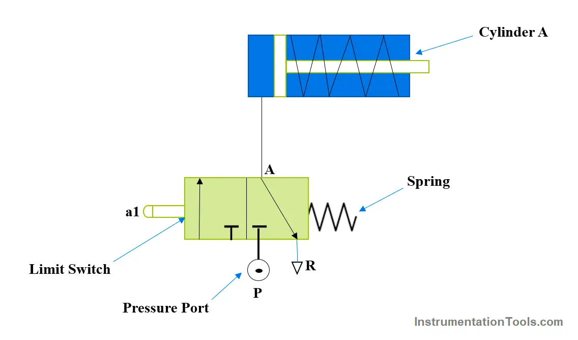
As per the diagram here, we have connected the limit switch in the series with the single-acting cylinder. So once the limit is pressed the air flow will go from A to port to cylinder and after that cylinder will move.
In the above circuit, we connected one single-acting cylinder in a pneumatic line series. Pneumatic air will be connected to the P port and the cylinder line relates to the A port of the 3/2 DCV. R is the exhaust port form where the air will be exhausted. Here the limit switch is a 3/2 valve.
Explanation
In this application, we want to learn how a limit switch works in the pneumatic circuit. In this application, as shown in the figure one limit switch (a1) relates to single-acting cylinder A via a pneumatic line or tube.
So once the limit switch is pressed by some object then air will move from P to A so it will push the cylinder piston outside, it is called the cylinder extracted condition. In another way, if the limit switch is released or the object is not in contact then Air will be exhausted from A to R It is called the cylinder retracted.
Put more simply, the single-acting cylinder can be triggered when the limit switch is pressed, completing the electrical circuit. Depending on the design and needs of the application, this activation may result in the cylinder extending or retracting.
On the other hand, the electrical circuit is open and the single-acting cylinder cannot operate when the limit switch is not pressed.
Components:
Cylinder
With their ability to provide regulated linear motion using the force of air or hydraulic fluid, single-acting cylinders are essential to automation.
Because of their single port design for fluid entry and external force design for the return stroke, they can be used in a variety of applications that call for dependability and simplicity.
Valve
The setup entails incorporating an air (or hydraulic) supply, a control valve, a single-acting cylinder, and a limit switch into the system. The limit switch is positioned so that, when pressed, it will cause the piston rod to extend.
When the single-acting cylinder extends to the required length, it stops on its own.
The single-acting cylinder’s return stroke is started by the control system upon releasing the Limit Switch (a1), concluding the cycle.
After an automatic reset, the single-acting cylinder is prepared for the subsequent operation.
Limit Switch
A limit switch connects an electrical circuit and a mechanical action or position. Limit switches fall into one of two categories:
Many kinds are based on the arrangements for contacts. It is activated when a piston rod, workpiece, or machine part is in a specific position. Typically, a cylinder piston or cam influences operation.
A limit switch provides two distinct events, the making of one contact and the breaking of the other. Limit switches are normally changeover contacts and can be used in three connection forms.
- A normally closed contact (N/C)
- A normally open contact (N/O)
Applications
Applications for this control arrangement can be found in many different industries, including assembly lines, manufacturing, and automated operations that call for accurate and controlled linear movements. Limit switch functioning is easy enough for operators of various ability levels to understand.
Door open-close application: – In industry doors, the open-close application is common, we can use this simple mechanism to implement it with a cost-effective solution.
Object sensing application: – In industry, there are several applications where objects need to touch the limit switch and the operation will start in that kind of operation, we can use this simple mechanism.
Advantages
This is a completely pneumatic system so it’s safe for the hazardous area. In some industrial applications and environments electric signals are not allowed due to hazardous zones so there we can implement this type of system.
We can use this system for door open-close systems where electrical signal is not allowed. Here we need completely pneumatic energy in the form of air so there is no need for an electrical supply. A compressor will supply air to the cylinder and cylinder movement will happen with pneumatic energy.
Air is used in this application, so it is clean and safe. In the case of the hydraulic system, there is a chance for oil leakage so it may impact the environment. The surrounding area becomes dirty due to oil and dust.
Oil will spoil the surrounding area so maintenance will increase for the components, and the time needed to clean components, so dust is also harmful to electronic components.
If you liked this article, then please subscribe to our YouTube Channel for Electrical, Electronics, Instrumentation, PLC, and SCADA video tutorials.
You can also follow us on Facebook and Twitter to receive daily updates.
Read Next:
- How to Select a Directional Valves?
- How to Choose a PLC for a Project?
- Moving Data between Siemens PLCs
- Proximity Switch Working Animation
- Free Cylinder Valve Sizing Calculator