The flow coefficient of a control valve (Cv) is a numerical value expressing the number of gallons per minute flow of water the valve will pass with a constant pressure drop of 1 PSI from inlet to outlet. This rating is usually given for the valve in its wide-open state.
For example, a control valve with a Cv rating of 45 should flow 45 gallons per minute of water through it with a 1 PSI pressure drop when wide open.
The flow coefficient value for this same control valve will be less than 45 when the valve position is anything less than fully open. When the control valve is in the fully shut position, its Cv value will be zero.
Thus, it should be understood that Cv is truly a variable – not a constant – for any control valve, even though control valves are often specified simply by their maximum flow capacity.
The basic liquid-flow equation relating volumetric flow rate to pressure drop and specific gravity is:

Where,
Q = Volumetric flow rate of liquid (gallons per minute, GPM)
Cv = Flow coefficient of valve
P1 = Upstream pressure of liquid (PSI)
P2 = Downstream pressure of liquid (PSI)
Gf = Specific gravity of liquid (ratio of liquid density to standard water density)
A common misconception is that Cv represents an absolute maximum flow rating for a valve. This is not true, any more than the resistance value of an electrical resistor reflects some maximum current value for that component. It is possible – at least in theory – to shove any rate of flow through any open valve given enough pressure to motivate that flow.
Cv, like electrical resistance measured in ohms, merely states the proportion between flow rate and pressure drop. Cv is simply the maximum flow rate of water through a control valve given a 1 PSI pressure difference from upstream to downstream.
It should be obvious that any control valve must be sized large enough (i.e. possess sufficient maximum Cv capacity) to flow the greatest expected flow rate in any given process installation.
A valve that is too small for an application will not be able to pass enough process fluid through it given the fluid pressure available.
Given this fact, it may seem safe to choose a valve sized much larger than what is needed, just to avoid the possibility of not having enough flow capacity.
Control Valve Sizing
For instance, consider this control valve sizing problem, where a characterized ball valve controls the flow rate of water out of a surge tank to maintain a constant water level 25 feet higher than the height of the valve:
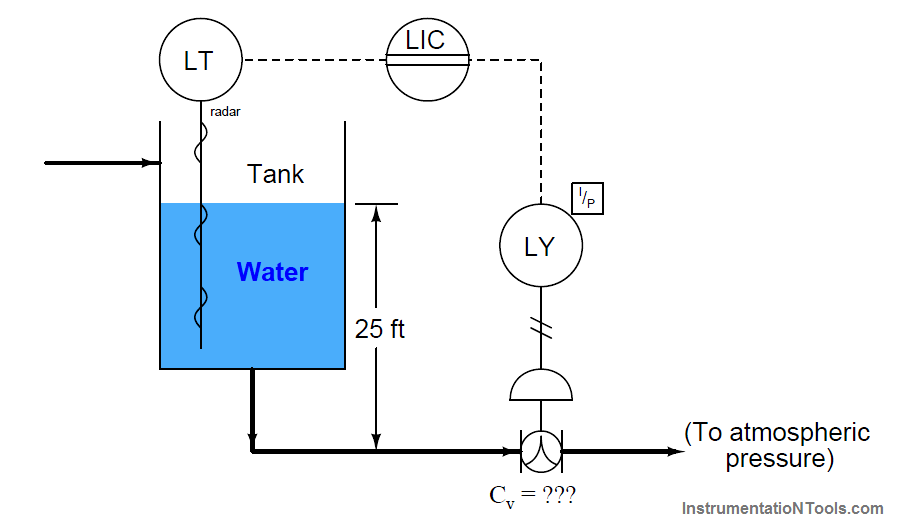
Suppose the process engineer designing this system specifies a maximum flow rate for this valve of 470 GPM. What should the maximum Cv rating be for this valve? To begin, we must know the expected pressure drop across the valve.
The 25 foot water column height upstream provides us with the means to calculate P1 by using the formula for calculating hydrostatic pressure (the pressure generated by a vertical column of liquid under the influence of gravity):
P = γh
P1 = (62.4 lb/ft3)(25 feet)
P1 = 1560 PSF = 10.8 PSI
There is no need to calculate P2, since the P&ID reveals the downstream side of the valve to be vented to atmosphere, and thus is guaranteed to be 0 PSI gauge pressure.
This gives us a pressure drop of 10.8 PSI across the control valve, with an expected maximum flow rate of 470 GPM. Manipulating our flow capacity equation to solve for Cv:
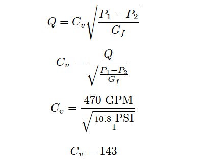
This tells us we need a control valve with a Cv value of at least 143 to meet the specified (maximum) flow rate.
A valve with insufficient Cv would not be able to flow the required 470 gallons per minute of water with only 10.8 PSI of pressure drop. As mentioned previously, these calculations yield approximate results only.
An analysis using computer-based valve sizing software may require an even larger control valve for this application.
Does this mean we should over-size the valve, just to ensure we don’t install one that is too small? For the sake of argument, would there be any problem with installing a control valve with a Cv value of 300? The general answer to these questions is that over-sized valves may create other problems.
Not only is there the possibility of allowing too much flow under wide-open conditions (consider whatever process vessels and equipment lie downstream of the oversized valve), but also that the process will be difficult to control under low-flow conditions.
In order to understand how an over-sized control valve leads to unstable control, an exaggerated example is helpful to consider: imagine installing a fire hydrant valve on your kitchen sink faucet. Certainly, a wide-open hydrant valve would allow sufficient water flow into your kitchen sink.
However, due to the gross mismatch between a fire hydrant valve’s flow capacity versus that of relatively skinny tubing providing water to the sink faucet, most of this valve’s usable range of throttling will be limited to the first percent of stem travel.
After the valve is opened just a few percent from fully shut, restrictions in the piping of your house’s water system will have limited the flow rate to its maximum, thus rendering the rest of the valve’s stem travel capacity utterly useless.
It would be challenging indeed to try filling a drinking cup with water from this hydrant valve: just a little bit too much stem motion and the cup would be subjected to a full-flow stream of water!
An over-sized valve is therefore an overly-sensitive valve from the perspective of the control system driving it. With the upper end of the valve’s travel being useless for control (having little or no effect), all the throttling action must take place within the first few percent of stem motion.
This makes precise control of flow rate more challenging than it should be. Typical valve problems such as stem friction, hysteresis, and calibration error therefore become amplified when the valve is over-sized, because any amount of imprecision in stem positioning becomes a greater percentage of the valve’s useful travel range than if the valve were properly sized and able to use its full range of motion.
Control valve over-sizing is a common problem in industry, often created by future planning for expanded process flow. “If we buy a large valve now,” so the reasoning goes, “we won’t have to replace a smaller valve with a large valve when the time comes to increase our production rate.”
In the interim period when that larger valve must serve to control a meager flow rate, however, operational problems caused by poor control quality may end up costing the business more than the cost of an additional valve.
The key here, as in so many other applications in business, is to carefully consider costs over the life-span of the device, not just the initial (capital) expense.
A practical solution to the problem of valve over-sizing – especially when larger flow rates will be required of the valve in the future – is to initially order the control valve with a body size suitable for the largest flow capacity it will need in the future, but equipped internally with reduced port (or restricted-capacity) trim.
This means trim having smaller holes (“ports”) through which the fluid must flow. Such “reduced” trim is under-sized for the valve body, making the control valve’s Cv rating significantly less than it would be with normal-sized trim installed.
The benefit of installing reduced-port trim in a control valve is that the flow capacity of the valve may be upgraded simply by removing the reduced trim components and replacing them with full-port (full-sized) trim.
Upgrading a control valve’s trim to full-port size is significantly less expensive than replacing the entire control valve with a larger one.
This is particularly true when one considers the piping changes usually necessary to accommodate a valve size change. Undersized valves installed in a pipe often require reducer fittings to “narrow” the full-bore size of the pipe down to the flange size of the control valve body. Upon replacement of the under-sized valve, these reducers must be removed to accommodate the larger valve body.
The piping itself may need to be cut and re-welded to match the flange-to-flange dimensions of the new (larger) control valve. All of this requires time, labor, and material investment. If a large valve body with reduced-port trim were initially installed, however, most of this time, labor, and expense could be avoided when the time comes to replace the reduced-port trim with full-port trim.
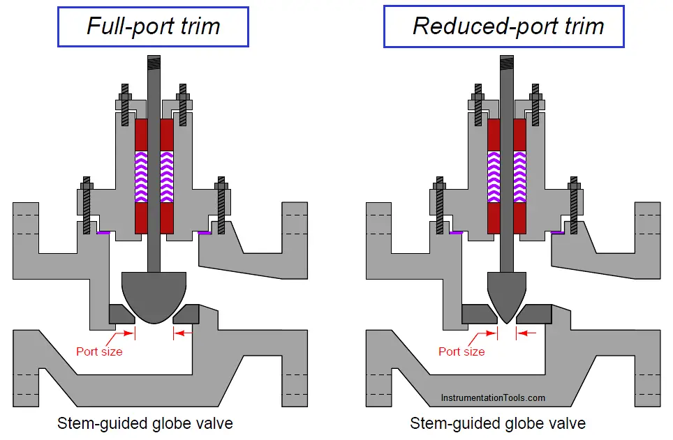
Reduced-port trim for a stem-guided or port-guided globe valve takes the form of a new (smaller) plug and seat assembly. The seat is specially designed to match the plug for tight shutoff and good throttling behavior, while having the necessary external dimensions to fit the larger valve body casting:
Reduced-port trim for a cage-guided globe valve often consists of nothing more than a new cage, having smaller ports in the cage than standard.
Thus, reduced-port trim for a cage-guided globe valve may utilize the exact same plug and seat as the full-port trim for the same cage-guided globe valve:
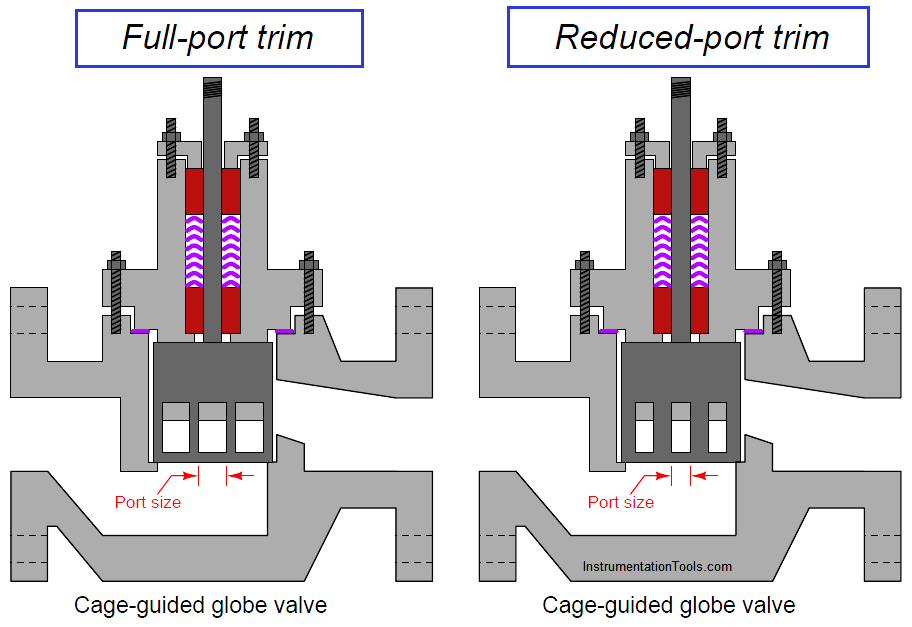
Reduced-port cage-guided trim may also take the form of a cage, plug, and seat of reduced diameter, with flanges attached in such a way that this smaller trim still fits inside the larger valve body.
The example illustrated here, with a full-diameter cage having narrower ports on it, is just one way of achieving reduced flow capacity in a cage-guided design but certainly not the only way.
Read Next:
- SIS Final Control Elements
- Choked Flow of Control Valves
- Pilot-operated Relief Valve Principle
- Control Valves Interview Questions
- Control Valves Leakage Classification
