Inst ToolsInst ToolsInst Tools
  • Courses
  • Automation
    • PLC
    • Control System
    • Safety System
    • Communication
    • Fire & Gas System
  • Instrumentation
    • Design
    • Pressure
    • Temperature
    • Flow
    • Level
    • Vibration
    • Analyzer
    • Control Valve
    • Switch
    • Calibration
    • Erection & Commissioning
  • Interview
    • Instrumentation
    • Electrical
    • Electronics
    • Practical
  • Q&A
    • Instrumentation
    • Control System
    • Electrical
    • Electronics
    • Analog Electronics
    • Digital Electronics
    • Power Electronics
    • Microprocessor
  • Request
Search
  • Books
  • Software
  • Projects
  • Process
  • Tools
  • Basics
  • Formula
  • Power Plant
  • Root Cause Analysis
  • Electrical Basics
  • Animation
  • Standards
  • 4-20 mA Course
  • Siemens PLC Course
Reading: Urea Reactor Top Bolted Plug developed Leaks
Share
Font ResizerAa
Inst ToolsInst Tools
Font ResizerAa
  • Courses
  • Design
  • PLC
  • Interview
  • Control System
Search
  • Courses
  • Automation
    • PLC
    • Control System
    • Safety System
    • Communication
    • Fire & Gas System
  • Instrumentation
    • Design
    • Pressure
    • Temperature
    • Flow
    • Level
    • Vibration
    • Analyzer
    • Control Valve
    • Switch
    • Calibration
    • Erection & Commissioning
  • Interview
    • Instrumentation
    • Electrical
    • Electronics
    • Practical
  • Q&A
    • Instrumentation
    • Control System
    • Electrical
    • Electronics
    • Analog Electronics
    • Digital Electronics
    • Power Electronics
    • Microprocessor
  • Request
Follow US
All rights reserved. Reproduction in whole or in part without written permission is prohibited.
Inst Tools > Blog > Root Cause Analysis (RCA) > Urea Reactor Top Bolted Plug developed Leaks

Urea Reactor Top Bolted Plug developed Leaks

After several years of service the urea reactor top bolted plug developed leaks. This root cause analysis solved the problem.

Last updated: September 28, 2022 3:08 pm
S Raghava Chari
Root Cause Analysis (RCA)
No Comments
Share
4 Min Read
SHARE

After several years of service the urea reactor top bolted plug developed leaks. This root cause analysis solved the problem.

Contents
Urea Reactor Top Bolted Plug LeaksCrew’s leak stop attemptRepair Attempts
Article Type:Root Cause Analysis (RCA)
Category:Mechanical
Equipment Type:Pipelines and Miscellaneous Problems
Author:S. Raghava Chari

Note: This root cause analysis (RCA) is from real-time scenarios that happened in industries during the tenure of two or three decades ago. These articles will help you to improve your troubleshooting skills and knowledge.

Urea Reactor Top Bolted Plug Leaks

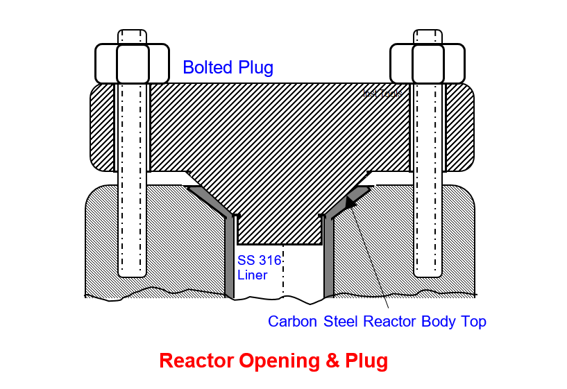
After several years of service the urea reactor 400 mm, dia x 280 mm thick top bolted plug (fig A) developed leaks.

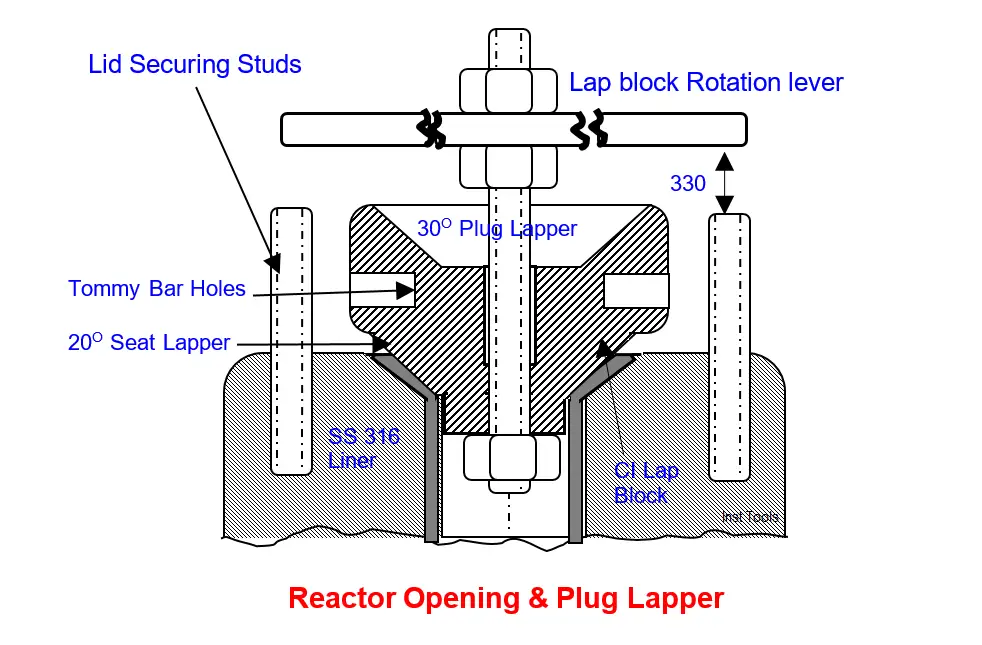
Tightening the studs loads the 30o included angle plug (fig B) and the 20o included angle reactor body opening conical portion line contact resulting in leak tight joint.

Crew usually repair such leaks by lapping the plug cone and reactor opening cone with a cast iron lap paste smeared lap block.

Usually the task takes several shutdown days. Since, the minor leak posed neither serious safety nor environment hazard; the plant lived with the leak awaiting a suitable repair opportunity.

Reactor Opening & Plug
Fig A

Crew’s leak stop attempt

Crew leader showed the CI lapping block showing only cone to lap the reactor 20o included angle opening using the reactor drawing given information (fig B), and another lap block for lapping the 30o plug sketch.  

The author appreciated the crew leader sketch. In addition, he suggested cutting the plug cone-lapping portion also on the same block to save costs. The lapping block was ready in few days.

Reactor Top lid lapped
Fig B

Repair Attempts

Severe draught forced an indefinite plant shutdown. The crew started the task. The leader reported two days later that two nos. cover studs defy unscrewing from the reactor body even with violent efforts. It would prevent Tommy bar Clockwise (CW) and CCW lap block rotation. Hence, lapping has not yet started.

The author chided himself for overlooking this possibility when he reviewed the lap block sketch.

He educated the crew to avoid unscrewing studs from vessels and valves as this could damage the body threads. Their repair is lengthy and time taking and often beyond field crew’s resources.

Site visit and few minutes thinking flashed him an idea: just drill a hole in the lapping block center and tighten a long stem to accept the Tommy bar well above the studs (fig B). Often site visits will generate ideas, which sometimes don’t occur on the office table drawing studies.

The crew lapped the reactor seat with the tall stem fitted lap block. They removed the stem, inverted the lap block and lapped the plug also. The entire task was over in a week working general shift hours only.

Operation crew 300 bars hydro-tested reactor with chlorides free condensate using the air operated piston pump that came with the plant. No leaks cheered all.

In addition, the crew learned the evils of violently unscrewing studs from vessel and valve bodies.

Author: S. Raghava Chari

Do you face any similar issues? Share with us through the below comments section.

If you liked this article, then please subscribe to our YouTube Channel for Instrumentation, Electrical, PLC, and SCADA video tutorials.

You can also follow us on Facebook and Twitter to receive daily updates.

Read Next:

  • Gas Cooler Re-tubing
  • Rotary Granulator Drive
  • Problems with Demister Pads
  • Steam Letdown Station Problems
  • Bucket elevators Chain Problems
Don't Miss Our Updates
Be the first to get exclusive content straight to your email.
We promise not to spam you. You can unsubscribe at any time.
Invalid email address
You've successfully subscribed !

Continue Reading

Critical High KiloWatt Motor Winding Burnout Threats
Pressure Correction Pneumatic Instrumentation
18 Temperature Sensors Fault Leads to Plant Shutdown
Root Cause Analysis for FRP Line Damaged due to On-Off Valve
Refrigeration Compressor Turbine Not-tripping when needed Trip
Fasteners and General Corrosion of Electrical Motors
Share This Article
Facebook Whatsapp Whatsapp LinkedIn Copy Link
Share
Leave a Comment

Leave a Reply Cancel reply

Your email address will not be published. Required fields are marked *

Stay Connected

128.3kFollowersLike
69.1kFollowersFollow
210kSubscribersSubscribe
38kFollowersFollow

Categories

Explore More

Minimum Oil Circuit Breaker (MOCB) No Vendor Spares & Service
Passing Control Valves Cause Yearly Losses in Production Plant
Gearbox within week Failing Journal Bearing upset Plant Operations
Compressor IP Case Discharge Temperature Gradually Increases
A Large Gate Valve’s Failed Motorized Operation
Compressor Cracked Shaft Spacers
Turbo-Compressor Problem – Root Cause Analysis
Control Panel Instruments Problem Threatened Plant Shutdown

Keep Learning

Target Flow Transmitter Problem

Target Flow Transmitters Failed the Very Midnight

Welding Machine Fail in Dusty and Corrosive Areas

Welding Machine Fail in Dusty and Corrosive Areas

Doubtful Temperature Readings

Doubtful Temperature Readings threatens Soaking Pit Wrecks 

Flash Vessel All Level Instruments Stopped Working

Ammonia Flash Vessel All Level Instruments Stopped Working

Less than 40% available Plant Air Compressors made available 100%

Less than 40% available Plant Air Compressors made available 100% for Operations

Replace Failed Motors Quickly and Easily

Replace Failed Motors Quickly and Easily

Piston No-Diaphragm Seal Instrument

Seal Pressure Instruments Root Cause Analysis

Vac Residue Tank Electrical Heating Element

Poor Electrical Heating Element Lives – Problem Solved

Learn More

Difference between Force and Power

Difference between Force and Power

Squirrel-Cage Induction Rotor

Induction Motor

Speed Control of Pneumatic Cylinder (Explanation with PLC)

Speed Control of Pneumatic Cylinder (Explanation with PLC)

Classification of Flow Measurement Techniques

Classification of Flow Measurement Techniques

System Architecture in Industrial Automation

How to Design a System Architecture in Industrial Automation?

PLC Stop - Start Circuit

Introduction to PLC Ladder Diagrams

PLC Sequential Operation Example Program

PLC Sequential Operation Example Program

Calculation of Hydrostatic Pressure

Calculation of Hydrostatic Pressure

Menu

  • About
  • Privacy Policy
  • Copyright

Quick Links

  • Learn PLC
  • Helping Hand
  • Part Time Job

YouTube Subscribe

Follow US
All rights reserved. Reproduction in whole or in part without written permission is prohibited.
Welcome Back!

Sign in to your account

Username or Email Address
Password

Lost your password?