In this article, you will learn the PLC to Start or Stop 3 Machines using 1 Switch basic PLC program.
Attention: The PLC example logic presented is for educational use exclusively for students and technicians to learn the basics.
PLC to Start or Stop 3 Machines
Problem Statement
Design a PLC ladder logic for the following application.
We are using one push button to control three Machines.
When the Push Button is pressed and then released, then Machine 1 will be ON.
When the Push Button is pressed again and then released, then Machine 1 will be OFF and Machine 2 will be ON.
When the Push Button is pressed again and then released, then Machine 2 will be OFF and Machine 3 will be ON.
PLC Training Videos
This video tutorial helps you to learn this example of programming from the basics.
I/O List
Digital Inputs:
The required inputs are listed below.
Push Button 1: I0.0
Digital Output:
The required outputs are listed below.
Machine 1: Q0.0
Machine 2: Q0.1
Machine 3: Q0.2
Ladder Diagram
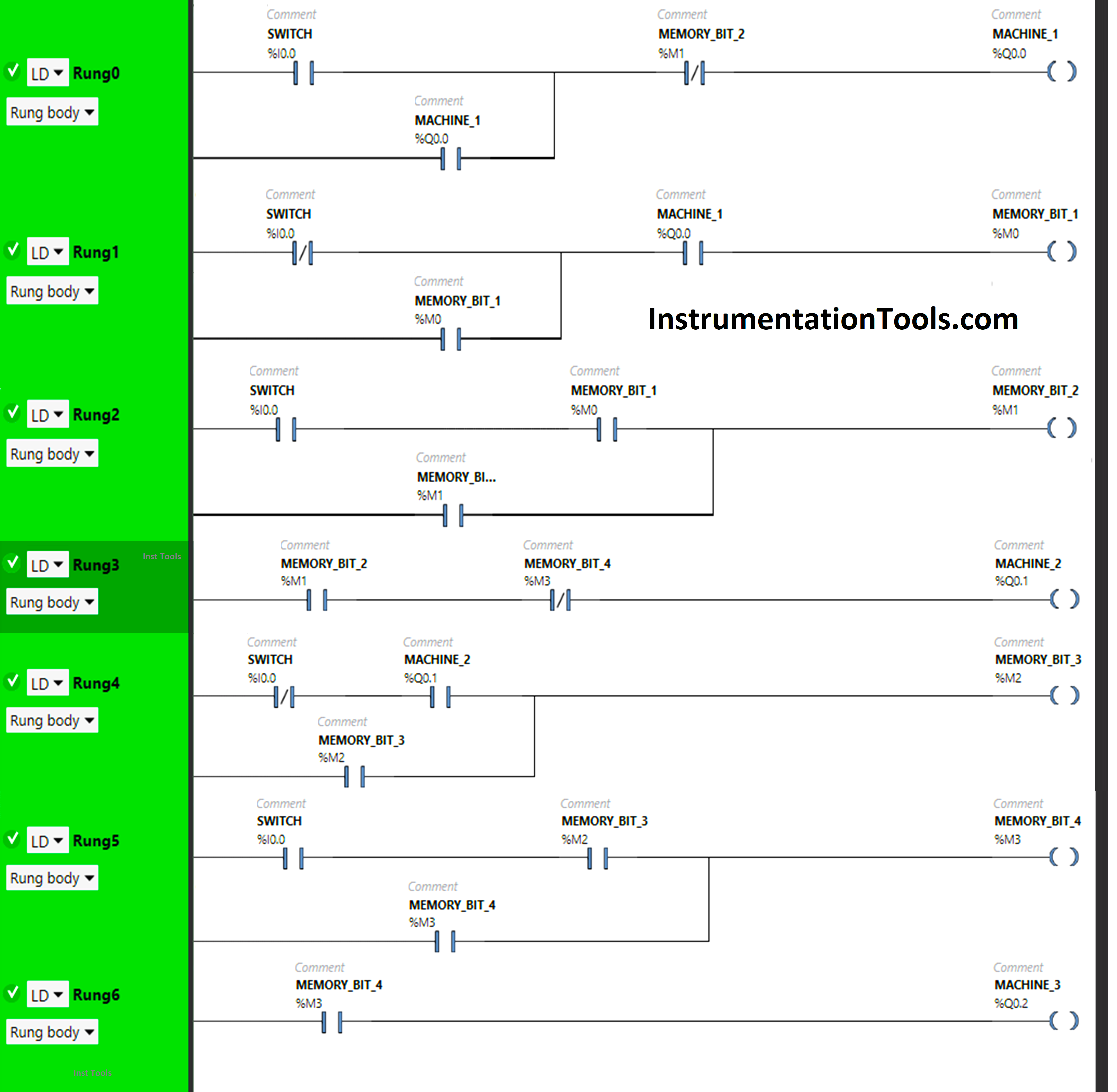
PLC Logic Description
- We used Schneider Electric PLC software.
- In the above program, we have used Normally Open Contacts as well Normally Closed Contact and Memory Bits.
- Normally Closed Contact is used for Memory Bit 2 in Rung0, Memory Bit 4 in Rung3 and for Push Buttons in Rung1 and Rung4.
- In Rung0, 1) Normally Open Contact is used for Push Button to turn ON Machine 1.
- Normally Closed Contact is used for Memory Bit 2 to turn OFF Machine 1.
- Latching is used for Machine 1 so that when Push Button is released, Machine 1 still remains ON.
In Rung 1:
1) Normally Closed Contact is used for Push Button and Normally Open Contact is used for Machine 1 to turn ON Memory Bit 1.
2) As Memory bit stores the data, Memory Bit 1 is used to store the data that Push Button has been released.
In Rung 2:
1) Normally Open Contacts are used for Push Button and Memory Bit 1 to turn ON Memory Bit 2.
2) As Memory bit stores the data, Memory Bit 2 is used to store the data that Push Button is pressed a second time.
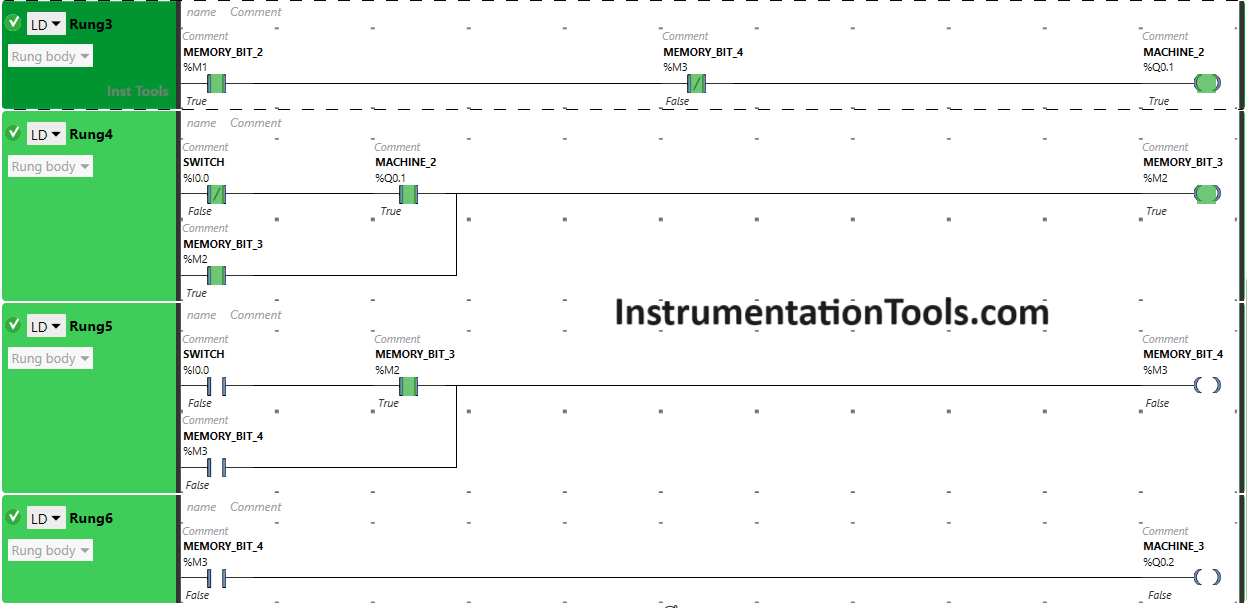
In Rung 3:
1) Normally Open Contact is used for Memory Bit 2 to Turn ON Machine 2.
2) Normally Closed Contact is used for Memory Bit 4 to Turn OFF Machine2.
In Rung 4:
1) Normally Closed Contacts are used for Push Button and Normally Open Contact is used for Machine 2 to turn ON Memory Bit 3.
2) As Memory bit stores the data, Memory Bit 3 is used to store the data that Push Button has been released a second time.
In Rung 5:
1) Normally Open Contacts are used for Push Button and Memory Bit 3 to turn ON Memory Bit 4.
2) As Memory bit stores the data, Memory Bit 4 is used to store the data that Push Button is pressed and released third time.
In Rung 6:
1) Normally Open Contact is used for Memory Bit 4 to Turn ON Machine 3.
So, When Push Button is pressed, signal will flow through it as Normally Open Contact is used for Push Button in Rung0. In false state, Normally Closed Contact used for Memory Bit 2 also passes the signal and Machine 1 will turn ON.
When Push Button is released, Machine 1 will remain ON as Latching is used for Machine 1 in Rung0. When Push Button 1 is released, Normally Closed Contact used for Push Button in Rung1 will be in false state and allows the signal to pass. Normally Open Contact Used for Machine 1 in Rung1 will also pass the signal as it is in True state and Memory Bit 1 will turn ON which is connected with Push Button and Machine 1 in Rung1.
When Memory Bit 1 will turn ON, it will store the data that Push Button has been released. When Push Button is pressed again, Memory Bit 1in Rung 1 will turn OFF and Memory Bit 2 in Rung2 and Rung3 will turn ON.
So, When Memory Bit 2 will turn ON in Rung 2, Normally Closed Contact used for Memory Bit 2 in Rung 0 will be in True state and Machine 1 will turn OFF and In Rung3, Machine 2 will Turn ON as Normally Open Contact used for Memory Bit 2 will be in True state and Normally Closed Contact used for Memory Bit 4 will be in false state.
When Push Button is released again, Machine 2 will remain ON as Normally Open Contact used for Memory Bit 2 in Rung3 will be in True state and Normally Closed Contact used for Memory Bit 4 in Rung3 will be in false state. In Rung4, Memory Bit 3 will Turn ON and will store the data that Push Button has been released second time.
Pressing and Releasing Push Button again will turn OFF Machine 2 because Memory Bit 4 in Rung3, Rung5 and Rung5 will turn ON and will store the data that Push Button has been pressed and released third time.
So, Normally Closed Contact used for Memory Bit 4 in Rung3 will be in true state and does not allow signal to pass to Machine 2. In Rung6, Machine 3 will turn ON as Normally Open Contact used for Memory Bit 4 in Rung3 will be in True State and pass the signal to Machine 3.
Result
The PLC program results with different input combinations are shown below. Please note that each image is unique and some images may not be shown all the rungs.
When Push Button is PRESSED
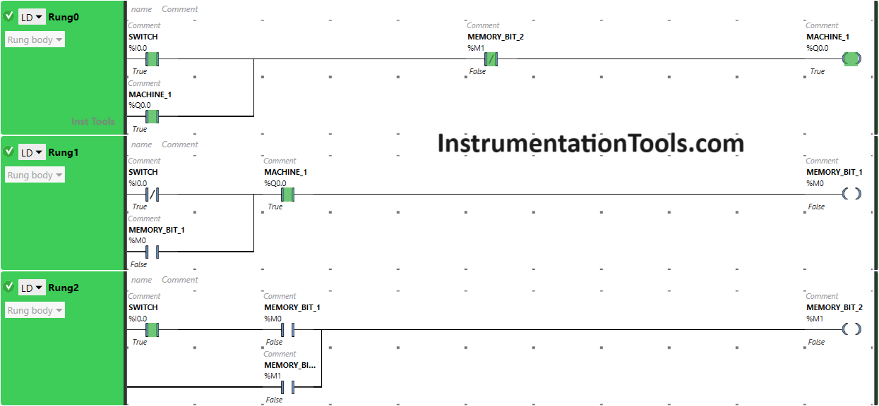
The signal flows through Push Button as it is in true state and Machine 1 will turn ON.
In false state, Memory Bit 2 in Rung0 also pass the signal to turn ON the Machine 1 as Normally Closed Contact is used for Memory Bit 2in Rung0.
When Push Button is RELEASED
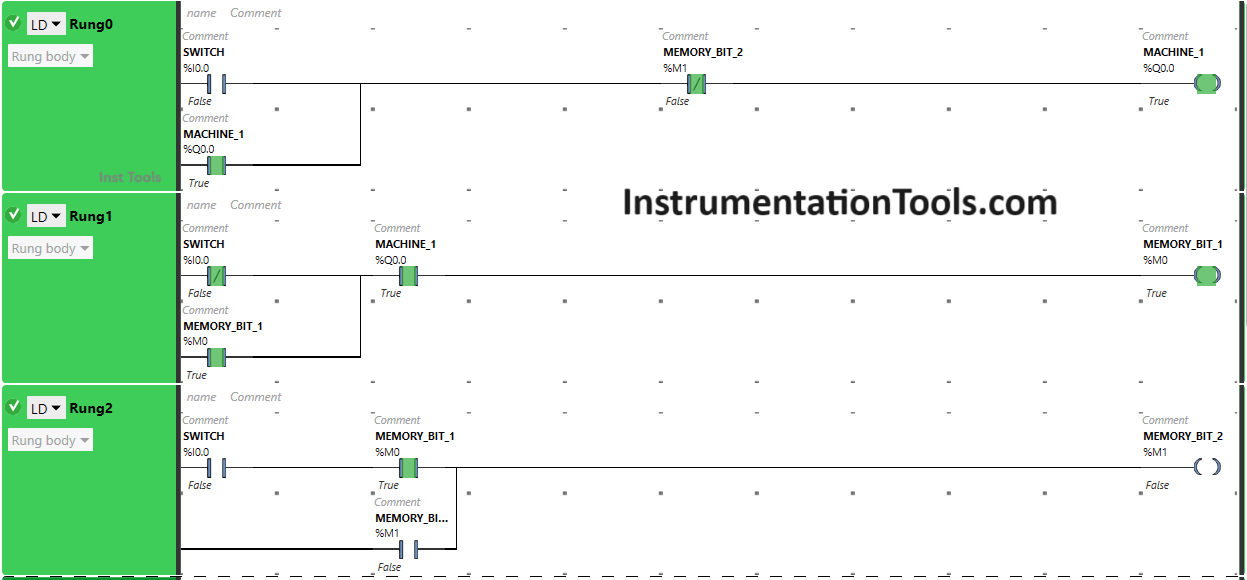
When Push Button I is released, Machine 1 will remain ON as Latching is used for Machine 1 in Rung0.
In Rung1, Memory Bit 1 will turn ON as Normally Closed Contact used for Push Button will be in false state and Normally Open Contact used for Machine 1 will be in True state.
Memory Bit 1 will store the data that Push Button has been released.
When Push Button is PRESSED Again (Second Press)
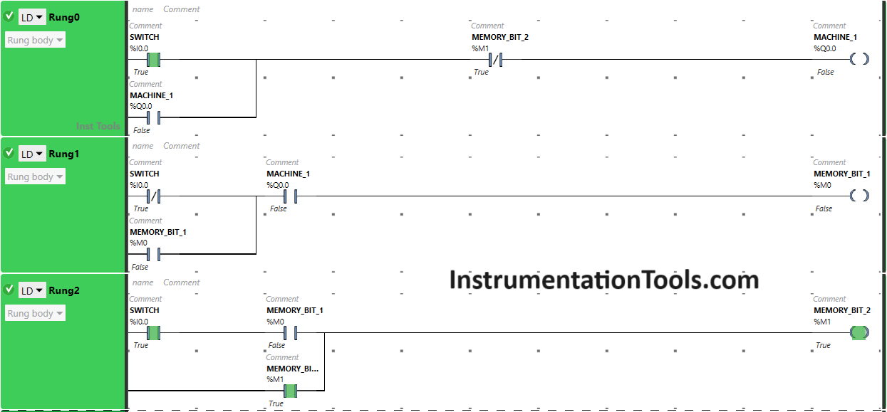
Pressing Push Button again will turn OFF Machine 1 because Memory Bit 2 in Rung0, Rung2 and Rung3 will turn ON and will store the data that Push Button has been pressed second time.
So, Normally Closed Contact used for Memory Bit 2 in Rung0 will be in true state and does not allow signal to pass to Machine 1.
In Rung3, Machine 2 will turn ON as Normally Open Contact used for Memory Bit 2 in Rung3 will be in True State and Normally Closed Contact used for Memory Bit 4 will be in false State.
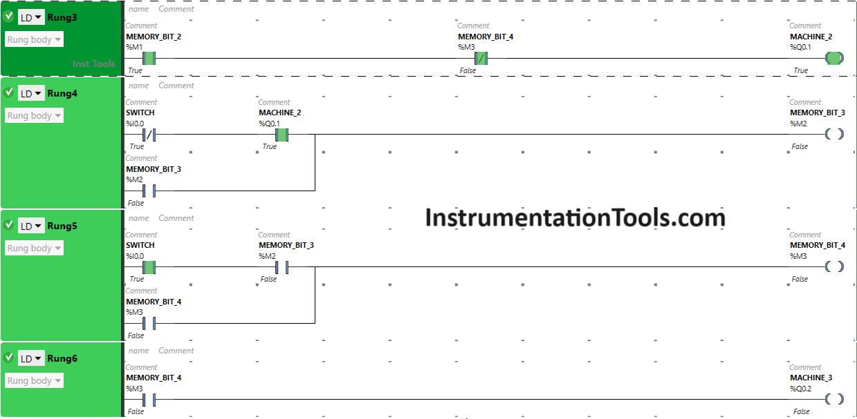
When Push Button is RELEASED Again (Second Release)
When Push Button is released again, Machine 2 will remain ON as Normally Open Contact used for Memory Bit 2 in Rung3 will be in True state and Normally Closed Contact used for Memory Bit 4 in Rung3 will be in false state.
In Rung4, Memory Bit 3 will Turn ON and will store the data that Push Button has been released second time.
When Push Button is PRESSED and RELEASED Again (Third Press and Release)
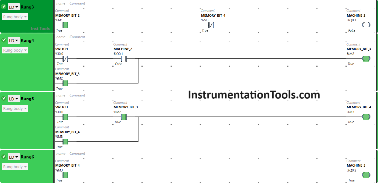

Pressing and Releasing Push Button again will turn OFF Machine 2 because Memory Bit 4 in Rung3, Rung5 and Rung5 will turn ON and will store the data that Push Button has been pressed and released third time.
So, Normally Closed Contact used for Memory Bit 4 in Rung3 will be in true state and does not allow signal to pass to Machine 2.
In Rung6, Machine 3 will turn ON as Normally Open Contact used for Memory Bit 4 in Rung3 will be in True State and pass the signal to Machine 3.
If you liked this article, please subscribe to our YouTube Channel for PLC and SCADA video tutorials.
You can also follow us on Facebook and Twitter to receive daily updates.
Read Next:
- Basic PLC Alarm Programming Example
- Run 4 Motors Push button PLC Program
- Start Stop of one Motor PLC program
- PLC Automatic Control of Two Outputs
- PLC Motor Logic with TEST Pushbuttons