PLC programming has five types of languages – ladder logic, instruction list, structured text, functional block diagram, and sequential flow chart. Each type of PLC language has its own merits and demerits. While some of the languages look good visually and are easy to troubleshoot, other languages have lower memory consumption and faster processing speed.
One of the most basic PLC languages used is the instruction list. It is not as famous as other languages and is used only by a few PLC programmers due to outdated technology, but still available in almost all the software of PLC manufacturers. In this post, we will see the concept of instruction list language in PLC.
What is an Instruction List?
A PLC program written in Instruction List language consists of a series of instructions that are executed sequentially by the logic controller. Each instruction is represented by a single program line and consists of the following components:
- Line number
- Current value (in online mode only)
- Instruction operator
- Operand(s)
- Optional comment
Basically, if you have seen traditional assembly language used in microprocessors, then you would easily relate to this language. It can also be termed as a mixture of ladder logic and structured text. Ladder logic in the sense that instructions must be written in a linear way, and structured text in the sense that mnemonics are used in words.
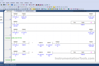
Refer to the below image for more understanding. The first image shows a PLC logic written in ladder language. The logic is – %M3 will turn on if %M0 is on and %M1 is on or %M2 is on.
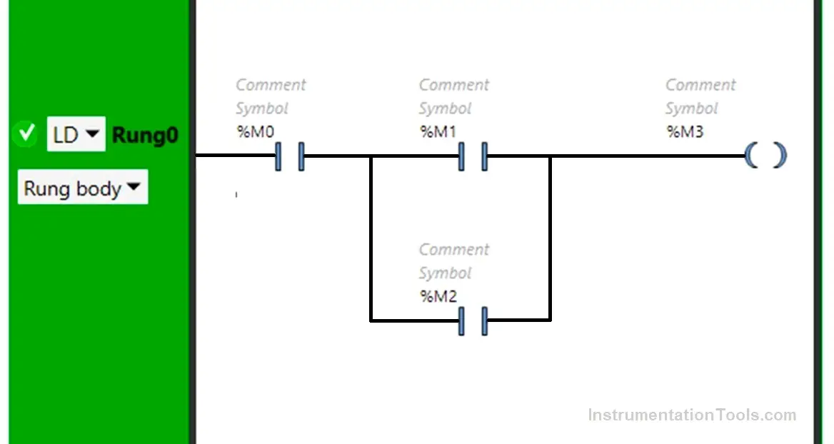
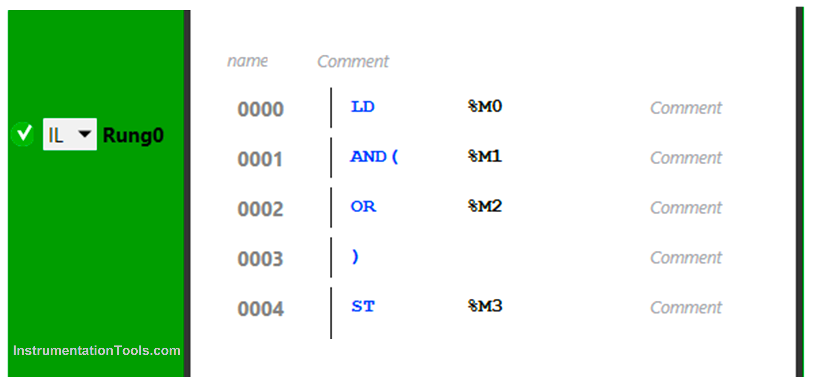
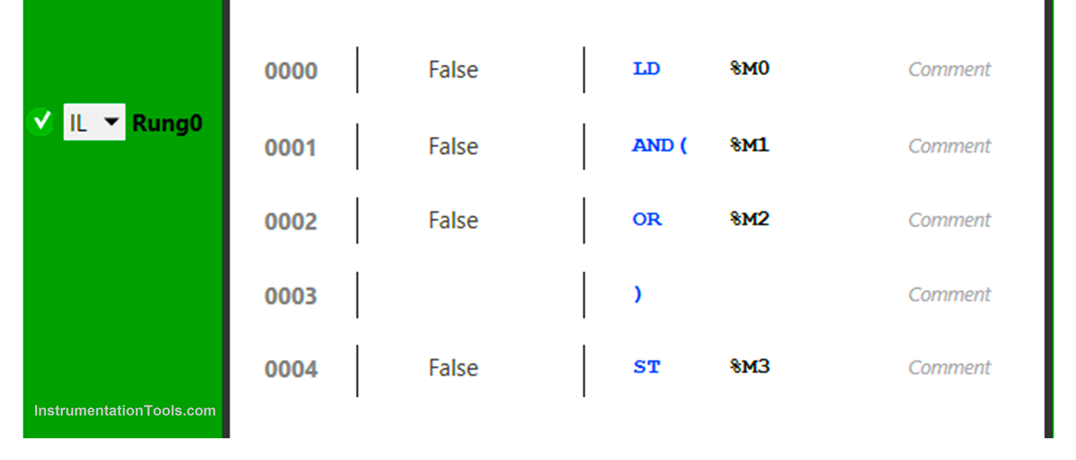
Now, refer to the below logic for the instruction list. You can see that each line has only one component – the first line has %M0, and the second line has %M1 doing AND logic with the next line.
The third line has %M2 doing OR logic with the previous line, the fourth line closes the commands and the fifth line turns on the output %M3. It is thus a representation of both the ladder logic and structured text.
Components of Instruction List
The main components of a PLC instruction list are mentioned below.
- Line number – Four-digit line numbers are generated when you create a new program line and are managed automatically by the software. It can be seen in the above figure as 0000 to 0004.
- Current values – In online mode, you can see the current values of each element, as shown in the below figure. It is indicated as true or false in the below image during online animation.
- Instruction operators – This operator is a type of command for executing an instruction. It can also be termed as the input side and output side of the logic written. It is a mnemonic symbol that is used to denote the type of command to be performed on the output side, and also how the output side will execute it. For example, in the above image, LD stands for load which starts the execution by loading the value of the first bit, AND / OR denotes logical instructions and ST denotes storing values of the result in the destination bit.
- Comment – This is optional. It allows the programmer to write any comment to help him troubleshoot the logic easily.
Instruction List in PLC Programming
Some of the instructions list of PLC are mentioned below.
- LD – Loads the Boolean value of the operand into the accumulator.
- LDN – Loads the negated Boolean value of the operand into the accumulator.
- LDR – Loads the Boolean value of the operand into the accumulator when the value changes from 0 to 1 (rising edge).
- LDF – Loads the Boolean value of the operand into the accumulator when the value changes from 1 to 0 (falling edge).
- AND – It performs an AND operation between the previous result and the current operand.
- ANDN – It performs an AND operation between the previous result and the inverse of the current operand.
- ANDR – It performs AND operation between the previous result and the rising edge of the current operand.
- ANDF – It performs an AND operation between the previous result and the falling edge of the current operand.
- OR – It performs OR operation between the previous result and the current operand.
- NOT – It performs the inverse operation of the operand.
- ST – It takes the value of the result generated.
- STN – It takes the inverse value of the result generated.
- S – It does the set operation of the operand.
- R – It does the reset operation of the operand.
Apart from these, it has other instructions too like jump, subroutine, end, AND with, OR with, etc. depending on the PLC manufacturer.
In this way, we saw the concept of the instruction list in PLC programming.
If you liked this article, then please subscribe to our YouTube Channel for Instrumentation, Electrical, PLC, and SCADA video tutorials.
You can also follow us on Facebook and Twitter to receive daily updates.
Read Next:
- PID Controllers Explained
- Comparison of Control Loops
- Top Best Practices of PLC Wiring
- Site Commissioning Steps for PLC
- Top 100 PLC Projects for Students